C5535 DSPShield H/W Reference Manual
Version 0.1
In Collaboration with Stanford University
page
14
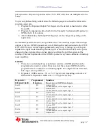
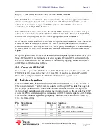
Port0.6
O
LED2: 0=OFF, 1=ON
Port0.7
O
Pull Down
Resistor on Pin
DSP_SPI_EN
0=Arduino SPI TXB0104 Transceiver Disabled
1=Arduino SPI TXB0104 Transceiver Enabled
Default = 0
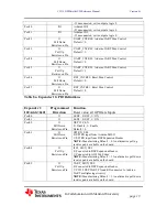
Port1.0
I/O
DSP Expansion Header PIN6
- If unconnected, set to output a logic 0
Port1.1
I/O
DSP Expansion Header PIN4
- If unconnected, set to output a logic 0
Port1.2
I/O
DSP Expansion Header PIN5
- If unconnected, set to output a logic 0
Port1.3
I/O
DSP Expansion Header PIN3
- If unconnected, set to output a logic 0
Port1.4
I
State of switch 4 on DIP Switch SW1
Port1.5
I
State of switch 3 on DIP Switch SW1
Port1.6
I
State of switch 2 on DIP Switch SW1
Port1.7
I
State of switch 1 on DIP Switch SW1
Table 8b. Expander 2 GPIO Definitions
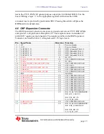
4.2 OLED Display
The OLED Display provides a 96x16 pixel display. It is programmed via the C5535
DSP’s I2C bus and has an I2C address of 0x3C.
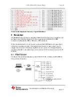
4.3 TLV320ACI3204 Audio Codec
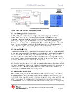
The AIC3204 Audio Codec interfaces to the C5535 DSP via the I2C and I2S2 buses. The
C5535 DSP’s I2S2 Bus is routed to the AIC3204 when I2S2_MUX_SEL = 1. The
AIC3204’s I2C address is 0x18.
The microphone stereo input is routed to the
Pink
jack, J1. The head phone stereo output
is routed to the
Green
jack, J2.
4.4 Micro SD Card Connector
Interface SD0 is connected to a micro SD card connector, P2. The micro SD card is the
default boot source for the C5535 DSP’s on-chip ROM Bootloader (RBL).
4.5 DIP Switch Inputs, LEDs and Push Button Reset
The status of switches 1, 2, 3 and 4 of DIP switch SW1, can be read by the C5535 DSP
via Port1.7, 1.6, 1.5, 1.4 of the GPIO Expander 2, respectively. “ON” corresponds to a
logic “1” in the GPIO Expander Input Register.
Three general purpose status LEDs are available for display by the C5535 DSP. They are
controlled by the output value of Port0.0, 0.1, and 0.6 of GPIO Expander 2. They
correspond to LEDs labeled as LED0, LED1 and LED2 on the board. A separate LED is


