Performance Test
51
6.2.5 Test Procedure
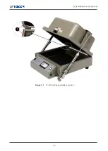
Before measuring, check the shielding gasket around the lid. If there is a damaged part,
replace the gasket and wipe the contact area, which is between the lid and the body except
the gasket, with alcohol.
1
Turn the spectrum analyzer and signal generator on.
2
Using an RF cable, connect the RF Connector(N Type) on the rear side of TC-5916AP Shield Box
to the RF output port(N Type) of signal generator.
3
Open the Shield Box lid and connect the 900 MHz Source Dipole Antenna to RF Port(SMA Type)
inside the Shield Box. (Place the antenna at the center of the Shield Box.)
4
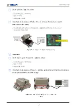
Set the output of signal generator to CW900 MHz, 10 dBm.
5
Connect the test antenna to the spectrum analyzer.
Summary of Contents for TC-5916AP
Page 1: ...TC 5916AP Pneumatic Shield Box User Manual R20190930...
Page 5: ...Revision History v Revision Record Revision Description Date v1 0 Initial Release 2019 09 23...
Page 9: ...PART 1 Getting Started 1...
Page 13: ...PART 2 Hardware Description 5...
Page 18: ...10 Dimension 2 2 Dimension...
Page 19: ...Dimension 11...
Page 25: ...PART 3 Putting into Operation 17...
Page 55: ...PART 4 Maintenance 47...
Page 63: ...Expendables and Accessories 55 Figure 7 1 TC 5916AP Expendables Location...

