Component Identification
9
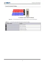
2.1.2 TC-5916AP Control Box
Figure 2-4
5916AP Control Box
Table 2-4
TC-5916AP Control Board Connector
No.
Function
Connector
Description
1
RS-232C Communication
JP2
RS-232C Connector
2
Power Supply
JP1
+24V DC Input Connector
3
LED
JP15
FAIL LED Connector
4
JP14
PASS LED Connector
5
JP13
TEST LED Connector
6
Solenoid Valve
JP11
Solenoid Valve Connector for Handler
7
JP10
Solenoid Valve Connector for Probe
8
JP9
Solenoid Valve Connector for Lid
JP8
Solenoid Valve Connector for Lid
9
Sensor
JP21
Lid Close Detection Sensor Connector
10
JP7
Handler Inward Detection Sensor Connector
11
JP6
Probe Downward Detection Sensor Connector
12
Operation Button
JP4
Right-Hand Side Lid Open Button Connector
13
JP5
Left-Hand Side Lid Open Button Connector
14
JP16
Fixture Operation Button Connector
Summary of Contents for TC-5916AP
Page 1: ...TC 5916AP Pneumatic Shield Box User Manual R20190930...
Page 5: ...Revision History v Revision Record Revision Description Date v1 0 Initial Release 2019 09 23...
Page 9: ...PART 1 Getting Started 1...
Page 13: ...PART 2 Hardware Description 5...
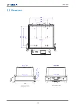
Page 18: ...10 Dimension 2 2 Dimension...
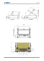
Page 19: ...Dimension 11...
Page 25: ...PART 3 Putting into Operation 17...
Page 55: ...PART 4 Maintenance 47...
Page 63: ...Expendables and Accessories 55 Figure 7 1 TC 5916AP Expendables Location...

