


3
1.2 Design Concept
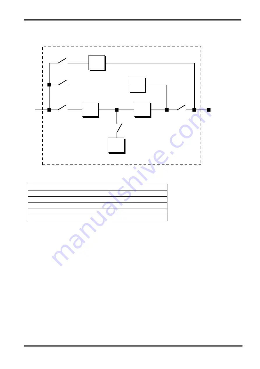
S1
:
Rectifier
input power switch
S2
: Static by-pass input power switch
S3
: Maintenance by-pass power switch
S4
: UPS power
output
switch
S5
: Battery circuit breaker (optional)
S6
: Static By-Pass control switch (Figure 1.3.a-b)
RECTIFIER:
The first conversion stage (from AC to DC) uses a 3 phase, fully controlled rectifier to convert the
incoming mains supply into a regulated DC BUS BAR. The DC BUS BAR produced by the rectifier provides both
battery charging power and power to the inverter section.
BATTERY GROUP:
It keeps as an reserve DC power supply, for the inverter in case of mains failure.
INVERTER:
It is made by utilizing the latest technology of power transistor (IGBT) and pulse width modulation
(PWM). Inverter converts dc bus voltage into (second conversion) an alternative voltage like line voltage. And
provides this voltage and frequency being fixed.
STATIC TRANSFER SWITCH (STATIC BY-PASS):
Two types of bypass circuitry is available for T300P series
UPS
•
Full static switch for parallel systems
•
Half static switch for normal UPS
The circuit block annotated contains an electronically controlled switching circuit, which enables the critical load
to be connected either to inverter output or to a by-pass power source via the” static by-pass line”. Normally at
standart models, the load is connected to the inverter via a contactor K1 (controlled by the static switch
circuits); but in the event of a UPS overload, or inverter failure, it is automatically transferred to the static by-
pass line.
In parallel systems the second static switch is builded, from inverter output, to load.
Inverter
Rectifier
Static By-pass
Static Transfer Switch
Maintenance By-pass
Mechanic Transfer Switch
3 Phase
Line
Input
3 Phase
Load
Output
Battery Group
S3
S2
S1
S5
S4
Figure 1-1
Block Diagram
Summary of Contents for T-300P Series
Page 2: ......
Page 36: ...32 Figure 5 5 a UPS Battery Group Connection With Battery Fuse To UPS Cabinet Battery Fuse...
Page 44: ...40...
Page 45: ...41 AGKK1831 11 2010...


