70
Handbuch / ManuHandbuch / ManuHandbuch / ManuHandbuch / ManuHandbuch / Manu
alalalalal
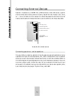
Examples of such connectors are the three CD-audio ports for Sony, Panasonic and Mitsumi.
This is where the internal audio output of the CD-ROM drive is connected. For the drives of the
above companies which do not meet the IDE standard, CN1 is applicable for Mitsumi, CN2 for
Panasonic and CN3 for Sony. In most IDE drives (including Mitsumi drives), the Panasonic
assignment has established itself as the audio port. However, as all CD-ROM manufacturers
have their own method, and as the assignations vary even within one product line, we
recommend that you consult the appropriate manual for information concerning the assignation
of the supplied audio cable.
If you have installed two CD-ROM drives, please use the slower drive of the two for audio CDs.
You can only use the audio ports alternatively as they are not isolated with respect to each
other. If you still want to use the audio output of the second drive, you are also able to connect
the audio output of the controller card or the headphone output of your drive to the „In-1“ input
of the soundcard.
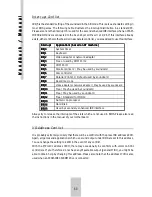
The soundcard has another four internal connectors which are connected in parallel with the
sockets on the cover panel. J2 corresponds to the audio output, J3 to the In-1 socket, J7 to the
In-2 socket and J9 to the Mic-In socket. Again, you may not use the internal and external input/
output simultaneously. Additionally there are the two internal connectors of both MPU-401
interfaces, J1 for MIDI1 and J10 for MIDI2. Here are the assignments of the internal connectors:
The utilization of the internal MIDI connections requires an additional electronic circuit, that
corresponds to the one used inside of the MIDI-kit. You will find the schematics in the annex.
Summary of Contents for Maestro 3296
Page 1: ...SoundSystem Maestro3296 Handbuch Manual...
Page 80: ......


