Compact Track Loader
13. Loader Disassembly and Assembly
13-7
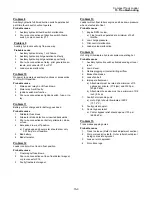
Figure 13-24
7.
Compress a replacement bushing to fit the hole
size and start the insertion with a dead blow
hammer as shown. As you drive the new
bushings into the lift arm, the old bushings will
be forced out of the opposite side of the lift arm.
Figure 13-25
8.
Complete the insertion of the first bushing with a
socket and hammer until the bushing is flush
with the surface of the lift arm.
9.
Repeat Step 8 to install the second
bushing. This action will force the remaining
worn bushing out and drive the first replacement
bushing to its permanent position.
10.
Clean and remove any debris, then apply
anti-seize to the inside of the bushings.
11.
Perform steps 7-10 on opposite side of lift arm to
remove remaining bushings.
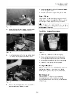
Figure 13-26
12.
With an assistant, lower lifting device to drop lift
arm back into position to re-install pins. A pry
bar may be used to aid in aligning chassis and
lift arm pin holes.
Figure 13-27
13.
Insert the pin into the chassis and through the lift
arm.
Figure 13-28
14.
Install bolt and nut to secure pin to chassis.
15.
Perform steps 12-13 for opposite side of lift arm.
Do not use fingers to align pin holes.
Summary of Contents for PT-30
Page 1: ...PT 30 Part Number 2010 513 Printed 1 11 Service Manual Compact Track Loader ...
Page 2: ......
Page 3: ......
Page 7: ......
Page 13: ...1 6 ...
Page 15: ......
Page 19: ......
Page 35: ......
Page 51: ......
Page 65: ......
Page 73: ......
Page 85: ......
Page 99: ......
Page 103: ......
Page 115: ......


