background image


 3-5 

3.3   Installation procedure 


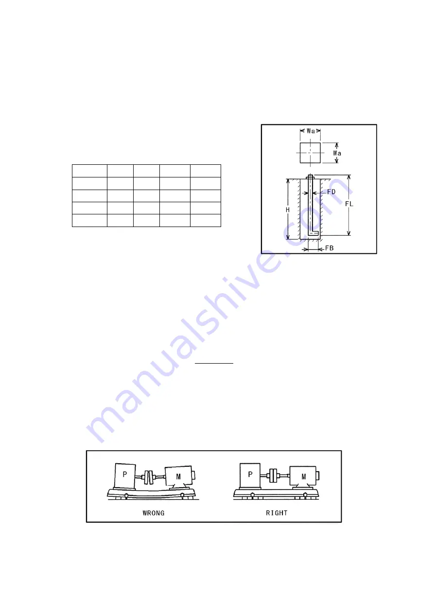
     (1)Provide a foundation of ample area and depth to bear the weight of the pump and its 

          operating load. 

     (2)Provide holes in the foundation in accordance with the drawings,or else using the 

          pump itself to determine the hole positions prior the pump is installed. 


          Anchor bolt and anchor bolt hole dimensions 


FD 

FL 

FB 

Wa 

M10 

200 

45 

100 

250 

M12 

250 

55 

120 

300 

M16 

315 

70 

150 

370 

M20 

400 

90 

190 

450 


     (3)Make sure that the surface of the concrete foundation is level,and protect it 

          thoroughly until the pump is installed. 

     (4)Mount the pump on the foundation.When mounting,insert square steel plates or 

          metal wedges between the common base and the concrete foundation,to make a gap 

          through which the mortar can be poured in.

(The gap should be 10-30 mm wide.) 


       As well as being used for adjusting the levelness of the pump,the metal wedges will 

       receive the pump's weight and operating load. 

       Use only a few wedges,that are as thick as possible. 

       Insert the wedges close to the anchor bolts,and locate them so that they provide 

       even weight. 


     (5)Fix the anchor bolts to the common base using the nuts,and hang them in center of 

          bolt holes.


N O T E 

3 - 2

Summary of Contents for SJ4S

Page 1: ...erstood this manual Keep this manual in a safe place where it can be consulted at any time To All mechanical Contracter Make sure to supply copies of this manual to the customer s operator maintenance...

Page 2: ...anticipated profits arising out of this contract or a breach thereof Seller does not warrant any auxialiary equipment The foregoing warranty does not cover and the Seller makes no warranty with respe...

Page 3: ...y instructions 1 2 1 Safety instructions for operation 1 2 2 Safety instruction for installation maintenance and inspection 1 3 Location of warning label Structure and overview of the pump 2 1 Names o...

Page 4: ...ons Safety instructions for operation 1 Before turning on the power always fit the cover over the motor terminal box There is danger of electric shock 2 Do not water motor It will cause short circuit...

Page 5: ...r of electric shock and the pump could start up suddenly causing injury Be sure to install an electrical leakage breaker on the power supply side 5 Turn off pump and cut off electric power call the sh...

Page 6: ...d ball bearing is housed in it Shaft coupling This coupling connects the pump and motor shafts transmitting the power It absorbs offset between the centers of the two shafts Shaft coupling protective...

Page 7: ...n bore size is 100 3m Impeller Closed Shaft seal Mechanical seal Structure Bearing Sealed ball bearing Casing SCS13 Shaft SUS304 Material Impeller SCS13 Type O D P or T E F C Type Motor Poles 2P 4P Po...

Page 8: ...ndary damage when water leakage happen 2 Fasten the pump securely on a concrete foundation using anchor bolts 3 Be sure to provide drainage ditch around the pump 4 If there is danger of freezing in th...

Page 9: ...s level and protect it thoroughly until the pump is installed 4 Mount the pump on the foundation When mounting insert square steel plates or metal wedges between the common base and the concrete found...

Page 10: ...s the gap under the common base and the area around the common base after alignment of shafts is completed When the mortar has fully cured tighten the anchor bolts Be sure to align the shafts correctl...

Page 11: ...7 If the pump is used for negative suction pressure do not install a sluice valve in the suction piping 8 If the pump is used for negative suction pressure install a foot valve equipped with a strain...

Page 12: ...utlet head FO Use possible material in considering the maintenance of pipes Set up the gate valves and the flow controlling valve for maintenance in flushing pipes Pressure flow muddiness of liquid ci...

Page 13: ...ower than 90 of the rating electric current The lowest currency should be 20Hz Do not drive inverter if motor is equipped with self protector Contract with us if 400V Measurement is necessary for inve...

Page 14: ...shaft by hand and check that it turns smoothly If it is not turned smoothly it means there are rust or foreign object inside the pump etc so inspect the pump 2 Fully open a sluice valve on suction pip...

Page 15: ...s could get caught up in the coupling Be sure to fix terminal box cover of motor There is danger of electric shock Do not run the pump in the reverse direction or it could break down Do not run the pu...

Page 16: ...igh stop start frequency is the reason for early damage of a pump Lessen the times of stop start frequency as much as possible 5 times per hour at MAX Keep the cocks of the pressure gauge compound gau...

Page 17: ...he pump is equipped with a mechanical seal there should be practically no dripping leakage of water from the seal If the mechanical seal does leak significantly replace it Make sure there is no abnorm...

Page 18: ...rtage of familiarity of mechanical seal slide surface This leak is not abnormalities of a mechanical seal Use the pump free from care About double mechanical seal 1 Do not drive double mechanical seal...

Page 19: ...ome less or more than the standard showed above Leakage quantity becomes more and more Re tightening the packing if the leakage is twice of the list showed above Exchange a new one if it won t be fast...

Page 20: ...crews Tighten Should be no looseness Clogging Should be no clogging Impellers Wear Disassemble and inspect Should be normal Shaft surroundings Smooth rotation Rotate by hand Should rotate easily Beari...

Page 21: ...mpany Insufficient priming water inside casing Prime thoroughly Air has got into suction piping Check suction piping joints Pump rotating in wrong direction Re wire to obtain correct direction Gate va...

Page 22: ...arings overheated Pump poorly installed shafts poorly aligned Re align correctly Impeller clogged with foreign matter causing imbalance Bearings worn or damaged Shaft is bent Cavitation has occurred P...

Page 23: ......

Page 24: ...Head Office 230 Moriwake Miyuki cho Fukuyama city Hiroshima 720 0003 Japan Tel 81 84 955 1111 Fax 81 84 955 5777 www teral net 2016 06 TP 246 01...

Reviews: