


115
T600/T600e 9016605 (04-2018)
TROUBLESHOOTING
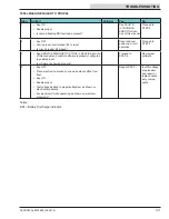
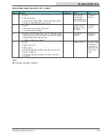
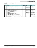
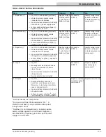
T600e i-DRIVE TESTING PROCEDURE
Step
Action
Value(s)
Yes
No
1
Switched (+)*
• Key ON / circuits loaded (preferred)
• All electrical components remain
connected to wire harness
• Use an electrical schematic to identify
all switched (+) power supply wires
• Is there
switched battery voltage
(+)
applied to circuit board?
Applied voltage
must be within
1 volt of actual
battery voltage
Proceed to
STEP 2
Identify voltage drop
location and repair
or replace necessary
components
1
2
Unswitched (+)*
• Key ON / circuits loaded (preferred)
• All electrical components remain
connected to wire harness
• Use an electrical schematic to identify
all unswitched (+) power supply wires
• Is there
switched battery voltage
(+)
applied to circuit board?
Applied voltage
must be within
1 volt of actual
battery voltage
Proceed to
STEP 3
Identify voltage drop
location and repair
or replace necessary
components
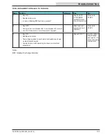
1
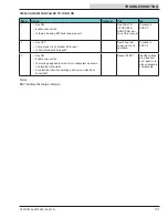
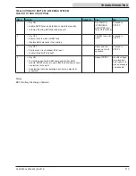
3
Negative (-)*
• Key ON / circuits loaded (preferred)
• All electrical components remain
connected to wire harness
• Use an electrical schematic to identify
all negative (-) / ground supply wires
• Is there battery negative (-) applied to
circuit board?
Applied voltage
must be within
1 volt of actual
battery voltage
Proceed to
STEP 4
Identify voltage drop
location and repair
or replace necessary
components
1
4
Inputs
• Key ON
• Manually exercise all input devices
and use a multimeter to observe
status change
• Use an electrical schematic to identify
all input circuits
• Do all inputs function correctly?
Proceed to
STEP 5
Repair or replace
necessary input
components
1
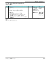
5
Outputs
• Key ON
• Disconnect battery and circuit
board from wire harness and use a
Ohmmeter to test output circuits for
open or shorted circuits
• Use an electrical schematic to identify
all output circuits
• Is there an
open
or
shorted
2
output
circuit causing the trouble symptom?
Repair or replace
necessary output
components
1
Replace circuit board
1
Wire harnesses are components
2
An open circuit has infi nite resistance “O.L.”. A
shorted circuit has 0 (zero) resistance. Always test
through entire circuit
* Switched (+) and Unswitched (+) indicate positive
battery voltage applied to circuit board. Negative (-)
indicates battery negative (ground) as part of power
supply to circuit board
Summary of Contents for T600e
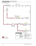
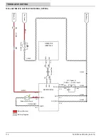
Page 13: ...T600 T600e 9016605 04 2018 13 GENERAL INFORMATION T600 ELECTRICAL SCHEMATIC PAGE 1 1 2 3 5 4...
Page 14: ...14 T600 T600e 9016605 04 2018 GENERAL INFORMATION T600 ELECTRICAL SCHEMATIC PAGE 2 1 2 3 5 4...
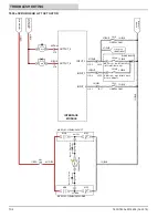
Page 15: ...T600 T600e 9016605 04 2018 15 GENERAL INFORMATION T600 ELECTRICAL SCHEMATIC PAGE 3 1 3 2...
Page 16: ...16 T600 T600e 9016605 04 2018 GENERAL INFORMATION T600 ELECTRICAL SCHEMATIC PAGE 4 1 2 3...
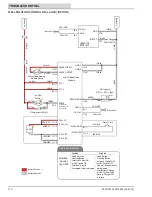
Page 17: ...T600 T600e 9016605 04 2018 17 GENERAL INFORMATION T600e ELECTRICAL SCHEMATIC PAGE 1 1 2 3 5 4...
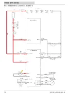
Page 18: ...18 T600 T600e 9016605 04 2018 GENERAL INFORMATION T600e ELECTRICAL SCHEMATIC PAGE 2 1 2 3 5 4...
Page 19: ...T600 T600e 9016605 04 2018 19 GENERAL INFORMATION T600e ELECTRICAL SCHEMATIC PAGE 3 1 2...
Page 20: ...20 T600 T600e 9016605 04 2018 GENERAL INFORMATION T600e ELECTRICAL SCHEMATIC PAGE 4 1 2...