


4-20
T12 Service Information 9009917 (12-12)
TROUbLESHOOTING
+
-
+
-
+
-
+
-
+
-
+
-
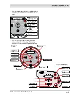
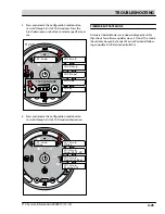
Scrub Head
Down
Enabled
• 1-STEP Scrub ON
• Squeegee/Vac ON
• 1-STEP Scrub OFF
• Squeegee/Vac OFF
• Recovery Tank Full
• Low Batt Voltage
• Load Current Fault
Disabled
Operational Matrix:
Scrub Head
Down
Enabled
• 1-STEP Scrub ON
• Fwd/Rev Propel
• 1-STEP Scrub OFF
• Neutral-Ready State
• Recovery Tank Full
• Solution Tank Empty
• Low Batt Voltage
• Load Current Fault
Disabled
Operational Matrix:
Tennant Quantum
UI ver1.0
Tennant Quantum
UI ver X.X
Tennant Quantum
UI ver X.X
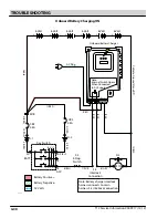
T16
Control
Board
6 Volt
Key Switch
IGN
15
ACC
30
BATT
Switched B+
From Buss Bar
75
50 Start
S-2
E-Stop
Switch
S-3
Charger
Interlock
ST
M1B
M1A
J7-1
B+(Control)
B+
B-
Battery Po
Battery Negative -
CAN +12V
J2-1
J2-2
J2-3
J2-4
RED #1
RED #2
BLK #2
BLK #1
CAN +
CAN -
CAN GR
OUND
D-4
D-2
D-3
CB1
2.5A
FU2
100A
6 Volt
6 Volt
6 Volt
6 Volt
6 Volt
CB2
2.5A
1/RED
13/BLK
6/BLU
7/PUR
Cable
Shield
Instrument Panel Assembly
Cable
3/OR
A
8/GR
Y
4/Y
EL
Cable t
o Gr
ound S
tand O
ff
5/GRN
10/T
AN
2/BRN
Cable
STP001
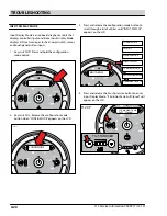
1. Turn Key Off.
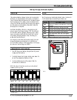
1 . key switch off . press and hold the configuration
mode button .
2 . key switch on . release the configuration mode
button when “ConfIG mode” appears on the LCd .
+
-
+
-
+
-
+
-
+
-
+
-
Scrub Head
Down
Enabled
• 1-STEP Scrub ON
• Squeegee/Vac ON
• 1-STEP Scrub OFF
• Squeegee/Vac OFF
• Recovery Tank Full
• Low Batt Voltage
• Load Current Fault
Disabled
Operational Matrix:
Scrub Head
Down
Enabled
• 1-STEP Scrub ON
• Fwd/Rev Propel
• 1-STEP Scrub OFF
• Neutral-Ready State
• Recovery Tank Full
• Solution Tank Empty
• Low Batt Voltage
• Load Current Fault
Disabled
Operational Matrix:
Tennant Quantum
UI ver1.0
Tennant Quantum
UI ver X.X
CONFIG MODE
T16
Control
Board
6 Volt
Key Switch
IGN
15
ACC
30
BATT
Switched B+
From Buss Bar
75
50 Start
S-2
E-Stop
Switch
S-3
Charger
Interlock
ST
M1B
M1A
J7-1
B+(Control)
B+
B-
Battery Po
Battery Negative -
CAN +12V
J2-1
J2-2
J2-3
J2-4
RED #1
RED #2
BLK #2
BLK #1
CAN +
CAN -
CAN GR
OUND
D-4
D-2
D-3
CB1
2.5A
FU2
100A
6 Volt
6 Volt
6 Volt
6 Volt
6 Volt
CB2
2.5A
1/RED
13/BLK
6/BLU
7/PUR
Cable
Shield
Instrument Panel Assembly
Cable
3/OR
A
8/GR
Y
4/Y
EL
Cable t
o Gr
ound S
tand O
ff
5/GRN
10/T
AN
2/BRN
Cable
STP002
1. Turn Key Off.
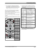
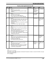
INPUT DISPLAY
CONFIG MODE
SELF TEST
MANUAL MODE
INPUT DISPLAY
CAN DIAG MODE
PROPEL DIAG MODE
FIRMWARE UPDATE
3 . press and release the configuration mode button to
scroll through a list of utilities until “InpuT dISpLay”
appears on the LCd .
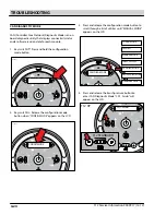
I1:Solution Tank
Full Closed
T12 STANDARD
T12 XP
4 . press and release the brush pressure button to enter
Input display mode . “I1:Solution Tank, full Closed” will
appear on the LCd .
Input display mode is an onboard diagnostic utility that
displays controller input conditions . Input display mode
displays LCd text messages for hard-wired switch, sensor,
and touch panel button inputs .
INPUT DISPLAY MODE
Summary of Contents for EC-H2O T12
Page 8: ...1 4 T12 Service Information 9009917 12 12 SAFETY PRECAUTIONS...
Page 68: ...3 44 T12 Service Information 9009917 12 12 MAINTENANCE...
Page 132: ...4 64 T12 Service Information 9009917 12 12 TROUBLESHOOTING...
Page 177: ......
Page 178: ......