

OPERATION
2-12
285 MM191 (12---89)
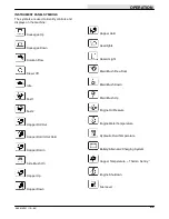
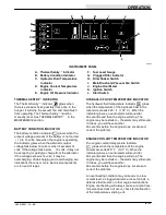
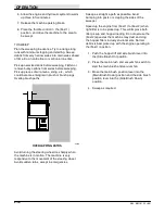
ENGINE OIL PRESSURE INDICATOR
The engine oil pressure indicator
glows when
the engine oil pressure falls below 5 psi (35 kPa).
When the indicator glows, an audio alarm will sound
for 30 seconds and then the engine will stop. The
engine may be restarted --- the alarm may still sound.
If it does, you will have another 30 seconds before
the engine stops. Locate and correct the problem.
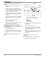
FUEL LEVEL GAUGE
The fuel level gauge
indicates how much fuel is
left in the fuel tank. It is present on gasoline and
diesel powered machines.
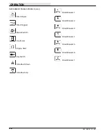
CLOGGED FILTER INDICATOR
The clogged filter indicator
glows when the
hopper dust filter is clogged.
To unclog the filter, shake it with the filter shaker
switch. If the filter shaker does not clean the filter
enough to turn the indicator off, clean the filter as
described in
HOPPER DUST FILTER
in the
MAINTENANCE
section.
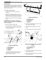
FILTER SHAKER SWITCH
The filter shaker switch
operates the hopper
dust filter shaker.
To unclog the hopper dust filter, push the filter shaker
switch. The filter shaker motor will then operate for
30 seconds. If the filter shaker does not clean the
filter enough to keep the clogged indicator off, try it
again. Then if the filter shaker does not clean the
filter enough to keep the indicator off, clean the filter
as described in
HOPPER DUST FILTER
in the
MAINTENANCE
section.
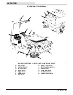
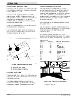
MAIN BRUSH AND VACUUM FAN SWITCH
The main brush and vacuum fan switch
controls hydraulic fluid flow to the main brush
and vacuum fan motors. The switch also controls the
scrub attachment, and the snow broom motor (only)
when the machine is equipped with the snow broom
accessory.
To start main brush rotation and vacuum fan suction,
press the switch.
To stop main brush rotation and vacuum fan suction,
press the switch again.
ENGINE HOUR METER
The engine hour meter
records the number of
hours the machine has been operated. This
information is useful in determining when to service
the machine.
IGNITION AND START SWITCHES
The key-operated ignition switch
controls power
to all machine electrical components. The start
switch
operates the engine starter motor.
To start the engine, turn the key fully clockwise. Then
press and hold the start switch until the engine
starts.
NOTE: Do not operate the starter motor for more than
10 seconds at a time or after the engine has started.
Allow the starter to cool between starting attempts.
The starter may be damaged if it is operated
incorrectly.
To stop the engine, turn the key counter-clockwise.
FOR SAFETY: Before starting machine make sure
all safety devices are in place and operate
properly.
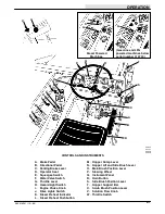
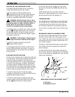
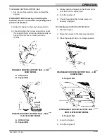
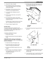
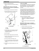
SIDE BRUSH POSITION LEVER
The side position lever controls the position of the
side brush.
To lower the side brush, pull the lever back and to
the left into the
(Side Brush Down) position. To
raise the side brush, pull the level back and to the
right into the
(Side Brush Up) position.
NOTE: Always raise the side brush when the machine
is not being operated for a period of time to prevent
the side brush from taking a set.
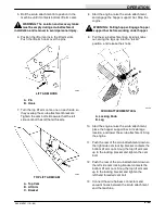
HOPPER SUPPORT BAR
The hopper support bar is located on the operator’s
side of the hopper. It holds the hopper in a “raised”
position to allow work to be done under the hopper.
Do not rely on the machine hydraulic system to keep
the hopper raised.
WARNING: Falling hopper. Engage hopper
support bar before working under hopper.
Summary of Contents for 285
Page 1: ...r 285 Sweeper Scrubber ...
Page 6: ...ABOUT THIS MANUAL 285 MM191 12 89 d ...
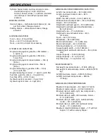
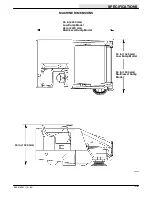
Page 18: ...SPECIFICATIONS 285 MM191 12 89 1 2 ...
Page 22: ...SPECIFICATIONS 285 MM191 12 89 1 6 ...
Page 24: ...OPERATION 2 2 285 MM191 12 89 ...
Page 62: ...OPERATION 2 40 285 MM191 NIL ...
Page 76: ...MAINTENANCE 285 MM191 12 89 3 14 04644 HYDRAULIC SCHEMATIC LOW DUMP MODEL ...
Page 77: ...MAINTENANCE 3 15 285 MM191 12 89 04645 HYDRAULIC SCHEMATIC MULTI LEVEL DUMP MODEL ...
Page 103: ...MAINTENANCE 3 41 285 MM191 6 90 06187 ELECTRICAL SCHEMATIC AUTO SHAKER RFS ...
Page 104: ...MAINTENANCE 285 MM191 6 90 3 42 06187 ELECTRICAL SCHEMATIC AUTO SHAKER RFS ...
Page 134: ...APPENDIX 285 MM191 12 89 4 2 ...


