OPERATION
2-17
285 MM191 (12---89)
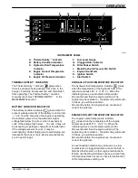
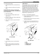
TO DUMP HOPPER
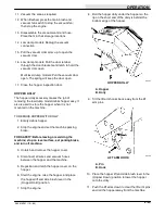
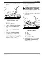
1. Pull the main brush position lever back into the
(Main Brush Up) position.
2. Pull the side brush position lever back into the
(Side Brush Up) position.
3. Press the main brush and vacuum fan switch to
stop the main brush and vacuum fan.
4. Press the filter shaker switch.
5. Slowly drive the machine up to the dump site or
dumpster.
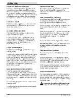
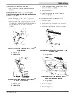
6. Low dump model machines: Pull the hopper lift
and side brush lever back into the (Hopper Up)
position to dump the hopper. Pull the lever into
the (Hopper Hold) position to keep the hopper
in the dumped position.
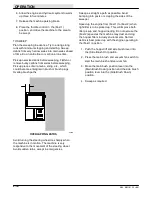
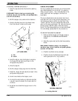
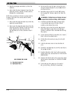
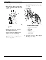
Multi-level dump model machines: Pull the
hopper lift and side brush lever back into the
(Hopper Up) position to lift the hopper to the
desired height. Be aware, the minimum vertical
clearance needed to high dump the hopper
108 in (2745 mm).
WARNING: Machine hopper lifts to 108 in
(2745 mm) when high dumping. Hopper can
hit overhead wires or object. Electrical shock or
falling debris can result. Be sure adequate
clearance is available before raising hopper.
Multi-level dump model machines: Pull the
hopper lift and side brush lever back into the
(Hopper Hold) position to keep the hopper at
the desired height; then push the hopper dump
lever into the (Hopper Roll Out) position to
dump the hopper.
NOTE: Lowering the hopper into the dumpster may
help to control flying dust.
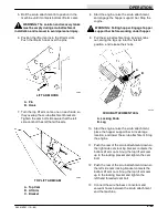
Multi-level dump model machines: Pull the
hopper dump lever into the (Hopper Roll In)
position to return the hopper to its normal
angle, then release the lever.
7. Push the hopper lift and side brush lever into
the (Hopper Down) position to return the
hopper to its operating position.
8. Slowly back the machine away from the dump
site or dumpster.
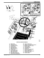
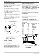
POST OPERATION CHECKLIST --- ENGINE
OPERATING
Check brush patterns for width and evenness.
TO STOP MACHINE
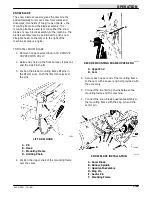
1. Return the directional pedal to the “neutral”
position. Apply the brake.
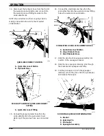
2. Pull the main brush position lever into the (Main
Brush Up) position and the side brush position
lever into the (Side Brush Up) position.
3. Place the hopper lift and side brush lever into
the (Hopper Down) position.
4. Press the main brush and vacuum fan switch to
stop the main brush and vacuum fan.
5. Turn the operating lights off if used.
6. Gasoline and LPG powered machines: Place
the throttle control in the (Idle) position.
Diesel powered machines: Place the throttle
lever in the (Diesel Stop) position.
7. Set the machine parking brake.
8. Turn the ignition switch key counter-clockwise.
Remove the key.
FOR SAFETY: Before leaving or servicing the
machine; stop on level surface, set parking brake,
and turn off machine.
9. LPG powered machines: Close the LPG tank
liquid service valve.
POST OPERATION CHECKLIST --- ENGINE
STOPPED
Check skirts for damage, wear, and adjustment.
Check for wire or string tangled on brushes.
Check to make sure LPG tank service valve is
closed.
Check for LPG odor indicating a fuel leak.
Check under machine for leak spots.
Summary of Contents for 285
Page 1: ...r 285 Sweeper Scrubber ...
Page 6: ...ABOUT THIS MANUAL 285 MM191 12 89 d ...
Page 18: ...SPECIFICATIONS 285 MM191 12 89 1 2 ...
Page 22: ...SPECIFICATIONS 285 MM191 12 89 1 6 ...
Page 24: ...OPERATION 2 2 285 MM191 12 89 ...
Page 62: ...OPERATION 2 40 285 MM191 NIL ...
Page 76: ...MAINTENANCE 285 MM191 12 89 3 14 04644 HYDRAULIC SCHEMATIC LOW DUMP MODEL ...
Page 77: ...MAINTENANCE 3 15 285 MM191 12 89 04645 HYDRAULIC SCHEMATIC MULTI LEVEL DUMP MODEL ...
Page 103: ...MAINTENANCE 3 41 285 MM191 6 90 06187 ELECTRICAL SCHEMATIC AUTO SHAKER RFS ...
Page 104: ...MAINTENANCE 285 MM191 6 90 3 42 06187 ELECTRICAL SCHEMATIC AUTO SHAKER RFS ...
Page 134: ...APPENDIX 285 MM191 12 89 4 2 ...

