

- 9 -
APPENDIX I
PROTECTION FUNCTIONS
The UC8 implements system protection functions such as
indoor coil frost, extreme high and low pressures, rapid on-
off cycling of the compressors, loss of refrigerant and more.
The following applies to all protection functions except
where otherwise indicated:
Unit operating capacity may automatically be reduced
before a protection function is activated. Such a reduction
may be sufficient to prevent an actual trip from occurring.
When a compressor is stopped by a protection function it is
held off for a period of 3 minutes, after which it is allowed to
restart (provided the cause of the trip has cleared).
When a protection function is active and when a unit is
locked out the alarm relay output “FLT” is active.
More detailed information about protection functions and
troubleshooting refer to document “UC8 troubleshooting
information”, available for free download from the
temperzone internet website.
1
High pressure protection (HP)
OPA Econex units are fitted with high pressure transducers
connected to UC8 input HPT. A compressor is switched
off when the discharge line pressure reading exceeds
4151 kPa.
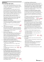
The display shows the letters ‘HP’ when protection is
active.
2
Low pressure protection (LP)
OPA Econex units are fitted with low pressure transducers
connected to UC8 input LPT. A compressor is switched off
when the suction line pressure reading falls below 228 kPa.
The display shows the letters ‘LP’ when
protection is active.
3
Indoor coil frost protection
When the unit is cooling the evaporating temperature in the
indoor coil should remain above -8°C. If this temperature
falls below -8°C then ice (frost) likely will form on the
indoor coil. If the low temperature persists for longer than 6
minutes then the protection function activates.
When indoor coil frost protection is
activated the compressor is stopped for 6
minutes, after which it is allowed to restart.
4
High discharge line temperature protection
The controller monitors the compressor discharge line
temperature via a sensor connected to input ‘DL’ (red wires).
The compressor is stopped when:
• The temperature rises above 115°C for longer than 15
minutes.
• The temperature rises above 125°C for longer than 2
minutes.
The display shows the message ‘Hi-t’ when
protection is active.
5
High discharge superheat protection
Discharge superheat is defined as the difference between
the compressor discharge gas temperature and the
condensing temperature. When this temperature differential
becomes very high it is an indication that the compressor
is being starved of refrigerant gas. Common reasons for
this could be a lack of refrigerant (under-charged or loss-
of-charge) or a problem with the expansion device (for
example a stuck accurator or loose wiring to an EEV).
The protection is activated when discharge superheat
exceeds 45K for longer than 30 minutes.
The display shows the message ‘Hi-dSH’
when protection is active.
6
Low discharge superheat protection
Discharge superheat is defined as the difference between
the compressor discharge gas temperature and the
condensing temperature. When this temperature differential
stays very low it can be an indication that the compressor
is being flooded with liquid refrigerant. Common reasons
for this could be an excess of refrigerant (over-charged) or
a problem with the expansion device (for example a stuck
accurator or loose wiring to an EEV).
The protection is activated when discharge superheat
remains below the threshold for longer than 15 minutes.
The threshold varies linearly from 0K at standard mode
minimum capacity (40%) to 10K at nominal capacity (100%).
This protection function is disabled when a compressor
operates at less than standard mode minimum capacity (<
40%).
The threshold for a variable speed compressor operated in
boost mode (capacity above 100%) is fixed at 10K.
The display shows the message
‘LO-dSH’ when protection is active.
7
High evaporation temperature / high suction line
temperature protection
When the unit has a low pressure transducer connected to
the compressor suction line then the controller calculates
the evaporating temperature from the suction line pressure
reading. If the unit does not have a low pressure transducer
then the controller finds the evaporating temperature
via a coil temperature sensor (input IC when the unit is
cooling, input OC when the unit is heating, blue wires).
Additionally the controller monitors the compressor suction
line temperature via a sensor connected to input ‘SL’ (white
wires).
The protection function stops the compressor when:
• The evaporating temperature remains above 27.5°C for
longer than 15 minutes.
• The suction line temperature remains above 30°C for
longer than 15 minutes.
The display shows the message ‘Hi-SL’
when protection is active.
8
Other alarms
The controller performs many other protection functions.
For example:
• Signals from sensors and transducers must remain inside
normal operating range.
• Modbus RTU communications with connected devices
(e.g. TZT-100 or SAT-3 thermostat, a Carel Power+
inverter) must continue uninterrupted.
• Modbus RTU communications with a controller such
as a BMS that is controlling the unit must continue
uninterrupted.
Refer to document ‘UC8 Troubleshooting Guide’ for details.


