

- 4 -
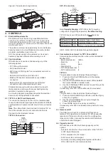
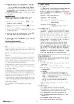
4.7 Unit Controller (UC8)
The unit’s UC8 controller receives requests such as ‘Unit
On/Off’, ‘Start compressors’, ‘Activate HEAT (Reverse
Cycle)’ and transfer the requests to the outputs after
enforcing safety timers.
Figure 4. UC8 Controller
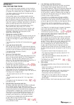
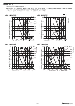
The Unit Controller provides several system protection
functions. These are covered in Appendix I (p.9).
For additional information, refer to the UC8 Controller label
on the unit or www.temperzone.biz for operation & fault
diagnostics information; model search ‘UC8’.
References available:
UC8 Operation Manual : Air-to-Air Units
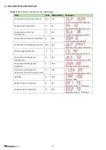
UC8 Fault & Display Messages (as per unit label)
UC8 Quick Reference and Operation Fault Diagnosis
UC8 Troubleshooting Guide
UC8 Modbus Communications
UC8 BACnet Communications
UC8 Master-Slave Connection
4.8 Control using switched and 0-10V signals
An external controller that provides 24V AC switched
signals or has a set of voltage-free relay contacts should
be connected as per the diagram below. UC8 inputs ‘VF’
and ‘VC’ will accept a 0-10V capacity control signals. If no
capacity control signal is available then link UC8 terminals
‘VF’ and ‘5’ and ‘VC’ and ‘12’.
BMS / external controller
Capacity
UC8
0-10V 0V
HIGH
MEDIUM
LOW
COMP2
COMP1
HEA
T
HI ME LO C1
CP HT C2
12 VC 0V
24V AC or 12V DC
24V AC COM or 0V
5 VF 0V
0-10V 0V
Comp.
Fan
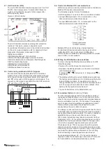
4.9 Control via Modbus RTU communications
OPA Econex units can be fully monitored and controlled via
Modbus RTU serial communications.
The following is typical for most installations:
• Set DIP switches 11 and 12 to OFF on all UC8 controllers.
• Connect BMS terminal A / TX+ to terminal A1 on the
UC8 controller via terminal block shown.
• Connect BMS terminal B / TX- to terminal B1 on the
UC8 controller via terminal block shown.
Multiple OPA units can be daisy-chained together.
For detailed information about monitoring and control
via Modbus RTU refer to document ‘UC8 Modbus
communications’, available at www.temperzone.biz (model
search ‘UC8’) or .com website.
4.10 Setting the UC8 Modbus device address
To view or change the Modbus device address of a UC8
follow these steps:
• Power up the unit but leave the compressors off.
• Hold down the SW3 pushbutton on the UC8 circuit board
until the display shows:
‘0’ [release] ‘1’ short press to ‘2,’ [long press] A,
[long press]
• The display will show the current Modbus device address.
The factory default address is ‘44’. [Short press] the button
to select higher numbers, for example press once to
change the address to 45, press twice for address 46 and
so forth. [Long press] to save the chosen address. After
address 99 the number returns back to 1.
• The controller returns to the default state (– ●).
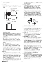
4.11 Economiser Option (Controls by Others)
The Economiser package that is factory fitted consists of
two opposed blade dampers, one for the fresh air and the
other for the return air and complete with individual damper
motors controllable from a 0 – 10V dc signal. The package
also includes a fresh air weathercowl supplied as a kitset
that must first be assembled, then fitted to the unitt –
usually before the unit is lifted into place.
The damper control will be factory wired such that the return
air damper will close proportionally as the fresh air damper
opens proportionally and vice versa. The fresh air damper’s
adjustable stop can be set such that it does not close
100%; many installations may require a minimum fresh air
introduction of 10 – 15% and the stop may be set on site to
facilitate this. Set the economiser Fresh Air Damper motor
‘stop’ to the equivalent negative static pressure as with
F/A damper closed. This is to ensure the air flow volume
remains constant and does not dramatically increase when
introducing fresh air. Failure to set the correct ‘stop’ position
could result in rain/moisture entrainment in the incoming
fresh air resulting in water deposited inside the unit.
As previously mentioned, a 0 – 10V dc control signal is
required to drive the dampers open and closed. This could
be from a BMS or a temperature/humidity controller.
LCD Display
Push button


