35
3–3 Configuring User Menu
Most conventional controllers are designed with a fixed order in which the parameters scroll. The
TEC-2500 has the flexibility to allow you to select those parameters which are most significant to
you and put these parameters at the front of the display sequence.
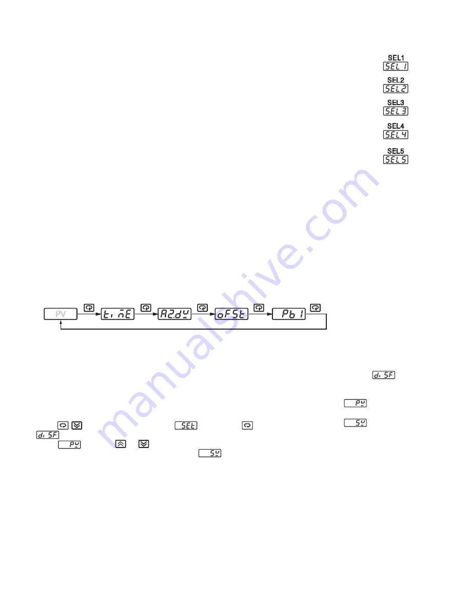
SEL1: Selects the most significant parameter for view and change.
SEL2: Selects the 2nd most significant parameter for view and change.
SEL3: Selects the 3rd most significant parameter for view and change.
SEL4: Selects the 4th most significant parameter for view and change.
SEL5: Selects the 5th most significant parameter for view and change.
Range: NONE, TIME, A1.SP, A1.DV, A2.SP, A2.DV, RAMP, OFST, REFC, SHIF, PB1, TI1,
TD1, C.PB, DB, SP2, PB2, TI2, TD2
When using the up and down keys to select the parameters, you may not see all of the above
parameters. The number of visible parameters is dependent on the setup condition. The hidden
parameters for the specific application are also deleted from the SEL selection.
Example:
A1FN selects TIMR
A2FN selects DE.HI
PB1=10
TI1=0
SEL1 selects TIME
SEL2 selects A2.DV
SEL3 selects OFST
SEL4 selects PB1
SEL5 selects NONE
Now, the upper display scrolling becomes:
3–4 Display SV Instead of PV
In certain applications where set point value (SV) is more important than process
value (PV), the parameter
DISF
(display format) can be used.
Press keys to enter setup menu , then press several times until
appears on the display. If you need the process value to be displayed, then
select by using or key while in DISF. If you need set point value
instead of process value displayed, then select for DISF. Refer to the flow
chart in section 1-5 to see the location of DISF.
SEL1
SEL2
SEL3
SEL4
SEL5
PV
DISF
has two values:
Display process value
Display set point value
Summary of Contents for TEC-2500
Page 2: ...NOTES...
Page 4: ...NOTES...
Page 10: ...6...
Page 11: ...7 1 5 Menu Overview...
Page 13: ...9 1 7 Parameter Description...
Page 14: ...10...
Page 16: ...12...
Page 17: ...13...
Page 18: ...14...
Page 19: ...15...
Page 20: ...16 NOTES...
Page 25: ...21 2 9 CT Heater Current Input Wiring...
Page 27: ...23 2 11 Output 1 Wiring Continued...
Page 29: ...25...
Page 31: ...27 2 14 Alarm 2 Wiring...
Page 32: ...28 2 15 RS 485...
Page 34: ...30 2 17 Analog Retransmission...
Page 35: ...31 2 18 Programming Port See figure 1 3 in section 1 3 to find the programming port location...
Page 36: ...32 NOTES...
Page 94: ...90 NOTES...
Page 96: ...92...
Page 97: ...93...
Page 98: ...94 NOTES...
Page 101: ...97 A 1 Menu Existence Conditions...
Page 102: ...98...
Page 103: ...99...
Page 104: ...100 A 2 Factory Menu Description...
Page 105: ...101 A 5 Memo Use the following table as a master copy for your settings page 1 of 2...
Page 106: ...102...


