background image

Istruzioni per 

l’uso

 e la manutenzione 

Motori elettrici 50-400 V CA


Pag. 

12 

di 

22 


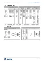
8.5


SERIE BTS, BPS, BTE e BPE con ENCODER / RESOLVER e 
CONNETTORE MIL 

CONNESSIONI DI POTENZA 


CONNESSIONI DI SEGNALE 

CONNETTORE MIL 

CONNETTORE MIL 

MOTORE 

FASE  U 

FASE  V 
FASE W 
MASSA 


FRENO 

POS.( + ) 

NEG.( - ) 


PTC 

(opzione) 

PTC 
PTC 


PIN M 

PIN  J 
PIN K 
PIN L 


PIN F 

PIN C 


PIN A 
PIN B 

RESOLVER 

2/8 POLI 

ENCODER con 

FASI di COMMUTAZIONE 

0 V 

V-Ref 

+ Cos 

 

- Cos 

 

+ Sin 

 

Sin 


Schermo  ( 
opzione ) 

PTC (opzione) 
PTC (opzione) 

PIN B 
PIN D 

PIN C 
PIN  E 
PIN G 
PIN H 
PIN  S 
PIN  A 
PIN N 

+5Vcc 

GND 

A neg. 

B neg. 

Z neg. 

Schermo 

PTC (opzione) 
PTC (opzione) 

PIN A 
PIN  B 

PIN  C 
PIN  D 
PIN  E 
PIN  F 
PIN G 
PIN  H 
PIN  S 
PIN  J 
PIN  K 
PIN M 
PIN P 

PIN V 

8.6


SERIE BTS, BPS, BTE e BPE con SENSORE di HALL e 
CONNETTORE MOLEX 

CONNESSIONI DI POTENZA 


CONNESSIONI DI SEGNALE 


CONNETTORE MOLEX 

SENSORE di HALL su CONNETTORE MOLEX 

MOTORE 


FASE  U 

FASE  V 
FASE W 
MASSA 


FRENO 

POS.( + ) 

NEG.( - ) 


PIN 1 
PIN 3 
PIN 2 
PIN 4 


PIN 5 
PIN 6 


+12Vcc 

GND 

Schermo 


PTC (opz) 
PTC (opz) 

PIN 1 
PIN 2 
PIN 6 
PIN 4 
PIN 3 
PIN 5 

PIN 11 
PIN 12 

Summary of Contents for 50-400 V CA Series

Page 1: ...A TEM ELECTRIC MOTORS s r l VIA BERETTA N 1 42024 Castelnovo Sotto RE ITALIA TEL 0522682723 0522688173 www tem electric motors com e mail info tem electric motors com MANUALE D USO E MANUTENZIONE ISTRUZIONI ORIGINALI Rev 0 del 20 10 2020 ...

Page 2: ...SOLVER e CONNETTORE MIL12 8 6 SERIE BTS BPS BTE e BPE con SENSORE di HALL e CONNETTORE MOLEX 12 8 7 SERIE BTS BPS BTE e BPE con SENSORE di HALL e CONNETTORE MIL o USCITA CAVO 13 9 PREPARAZIONE ALL UTILIZZO 14 9 1 Avvertenze prima dell avviamento 14 9 2 Avviamento ed arresto 14 9 3 AVVERTENZA PER MOTORI DOTATI DI FRENO DI STAZIONAMENTO 14 10 PROTEZIONE DEL MOTORE ELETTRICO 15 11 MANUTENZIONE E RIPA...

Page 3: ...ca e meccanica pertanto se utilizzato in modo improprio può creare condizioni di pericolo e causare danni a persone animali e cose Si raccomanda di leggere attentamente le istruzioni che seguono prima della messa in servizio del motore ogni operazione di installazione messa in servizio manutenzione e protezione del motore elettrico deve essere eseguita da personale qualificato nel rispetto di tutt...

Page 4: ...ambini e gli estranei a distanza di sicurezza durante il funzionamento di un apparecchio elettrico Non far funzionare apparecchi elettrici all aperto in presenza di pioggia nebbia temporale alte e basse temperature o in ambienti bagnati o umidi L utilizzo in queste condizioni può provocare la folgorazione In caso di dubbio in campo elettrico affidatevi ad un tecnico specializzato di comprovata esp...

Page 5: ...ali dati 1 Ragione sociale e indirizzo 2 Designazione della serie tipo 3 Giri per Minuto 4 Tensione nominale 5 Grado di protezione 6 Classe isolamento 7 Coppia nominale 8 Coppia di picco 9 Costante di tensione 10 Serial number 11 Mese e Anno di costruzione 12 Corrente nominale 13 Tensione alimentazione freno 14 Modello encoder 15 N poli resolver 16 Marcatura CE 17 Divieto di buttare nei rifiuti ur...

Page 6: ...cui è in possesso per fare questo è sufficiente fornire o il nome completo dell articolo vedi codice su casella TYPE della targa motore o il numero di matricola vedi matricola su casella P N della targa motore I dati tecnici quando non diversamente specificati si intendono riferiti a tolleranza 5 Temperatura ambiente 25 C Altitudine max 1000m s l m Umidità relativa max 75 in assenza di condensa 7 ...

Page 7: ...Prima di ogni operazione scollegare dalla rete elettrica il motore ed il suo equipaggiamento Possiede parti rotanti pericolose rimuovere le protezioni solo a motore scollegato dalla rete e con parti non in movimento Attenzione il motore può raggiungere nelle superfici esterne a contatto con l operatore temperature elevate Maneggiare solo a motore freddo Attenzione il motore ha parti taglienti che ...

Page 8: ...da vibrazioni resistente alle deformazioni 3 allineare con cura il motore e la macchina comandata per evitare sforzi inammissibili sull albero motore rispettando i carichi radiali e assiali massimi ammessi un disallineamento può provocare durante l esercizio surriscaldamenti anomali e o rotture meccaniche mettendo a rischio la sicurezza 4 durante il montaggio evitare danni al motore non sottoporre...

Page 9: ... le seguenti operazioni Verificare che la controflangia di accoppiamento sia della stessa grandezza e forma costruttiva di quella del motore Pulire le zone di contatto delle flange togliere la protezione sull albero motore e accertarsi che la chiavetta sia in posizione corretta Eseguire l accoppiamento tra il motore e l organo di trasmissione avendo cura di serrare tutte le viti sui fori della fla...

Page 10: ...ccertarsi che l impianto di alimentazione del servomotore sia fornito di messa a terra Effettuare con cura i collegamenti delle messe a terra e delle schermature facendo riferimento anche al manuale d uso e manutenzione dell azionamento I dati di targa del motore sono riferiti ad alimentazione con corrente sinusoidale Qualora l alimentazione sia di tipo differente trapezoidale occorrerà declassare...

Page 11: ...S PIN A PIN N 5Vcc GND A neg A B neg B Z neg Z Schermo PTC PTC PIN A PIN B PIN C PIN D PIN E PIN F PIN G PIN H PIN S PIN J PIN K 5Vcc GND A neg A B neg B Z neg Z Schermo PTC PTC V neg V W neg W U neg U PIN A PIN B PIN C PIN D PIN E PIN F PIN G PIN H PIN S PIN J PIN K PIN L PIN M PIN N PIN P PIN U PIN V 8 4 SERIE BTS BPS BTE e BPE con ENCODER e CONNETTORE MOLEX CONNESSIONI DI POTENZA CONNESSIONI DI...

Page 12: ...os Cos Sin Sin Schermo opzione PTC opzione PTC opzione PIN B PIN D PIN C PIN E PIN G PIN H PIN S PIN A PIN N 5Vcc GND A neg A B neg B Z neg Z Schermo PTC opzione PTC opzione V W U PIN A PIN B PIN C PIN D PIN E PIN F PIN G PIN H PIN S PIN J PIN K PIN M PIN P PIN V 8 6 SERIE BTS BPS BTE e BPE con SENSORE di HALL e CONNETTORE MOLEX CONNESSIONI DI POTENZA CONNESSIONI DI SEGNALE CONNETTORE MOLEX SENSOR...

Page 13: ...RRONE BIANCO NERO opz BLU BLU GRIGIO VERDE GIALLO NB Il senso di rotazione del motore è quello convenzionale rotazione oraria visto lato di potenza secondo EN 60034 8 NB Tutti i motori sono provvisti di morsetto o vite per la messa a terra evidenziato dal simbolo Il senso di rotazione del motore è quello convenzionale rotazione oraria visto lato di potenza secondo EN 60034 8 ATTENZIONE Verificare ...

Page 14: ...te le avvertenze riportate nei paragrafi successivi PREMESSA I motori equipaggiati con freno standard prevedono un freno a molle trattasi di freni statici ad azione inversa cioè la forza frenante viene applicata in mancanza di tensione 9 3 AVVERTENZA PER MOTORI DOTATI DI FRENO DI STAZIONAMENTO I freni utilizzati su tutti i motori sono dimensionati per mantenere bloccato il motore e non per eseguir...

Page 15: ...di sovraccarichi ma che non ha potere di interruzione sufficiente per i cortocircuiti in questo caso la relativa protezione e affidata a fusibili inseriti più a monte di tipo ritardato idonei per motori per tener conto delle sovracorrenti previste all avviamento Correnti di sovraccarico Deve essere prevista la protezione contro i sovraccarichi per tutti i motori usualmente in servizio continuo con...

Page 16: ...ne indispensabile quando la sovra velocità può causare condizioni di pericolo può essere ottenuta prevenendo tali funzionamenti anomali per esempio con l impiego di dispositivi sensibili alla velocita del motore interruttori centrifughi o relè di tensione collegati a dinamo tachimetriche che interrompano l alimentazione del motore eventualmente inserendo anche dispositivi di frenatura nel caso in ...

Page 17: ... massima corrente o interruttore differenziale collegamento di protezione effettuato secondo il sistema con conduttore di neutro collegato a terra all origine e usato come conduttore di protezione in questo caso non e possibile utilizzare la protezione differenziale e quindi debbono intervenire gli interruttori di massima corrente Consultare le norme specifiche Deve essere garantito il coordinamen...

Page 18: ...nella quale verrà inserito il motore ATTENZIONE Durante il funzionamento la struttura esterna del motore può raggiungere una temperatura vicina ai 90 C attendere quindi che si raffreddi prima di effettuare operazioni manuali ATTENZIONE Sconnettere elettricamente il motore prima di iniziare qualsiasi operazione su di esso Le parti interne ed esterne possono avere spigoli taglienti maneggiare quindi...

Page 19: ...ioni schermature Verificare il corretto inserimento dei parametri motore sul drive Verificare fasatura encoder resolver IL MOTORE IN FERMO IN COPPIA OSCILLA LIEVEMENTE Errato collegamento cavo del trasduttore Controllare connessioni encoder resolver Controllare connessioni schermature IL MOTORE GIRA IN MODO IRREGOLARE Presenza di disturbi Verificare la presenza nei pressi del motore di fonti di di...

Page 20: ...duzione come indicato sulla linea guida della UE per l applicazione della direttiva E M C La conformità alle norme sopracitate deve invece essere verificata per il pacchetto motore azionamento anche quando i due componenti presi singolarmente risultano conformi Per il corretto funzionamento del sistema inoltre i cavi di segnale e potenza devono essere schermati la schermatura deve essere con conne...

Page 21: ...cino 13 2 Mantenimento dei requisiti minimi Il costruttore garantisce il mantenimento dei requisiti minimi di sicurezza per anni 10 dieci dall anno di fabbricazione 13 3 Limiti della garanzia La ditta costruttrice garantisce i motori descritti nel presente libretto per 24 ventiquattro mesi dalla data riportata sulla targa del motore ed entro tale periodo si impegna a riparare o sostituire le parti...

Page 22: ... di 22 13 4 Certificato di garanzia CERTIFICATO DI GARANZIA TEM ELECTRIC MOTORS srl Articolo N di serie P N Data di acquisto Anomalia riscontrata Timbro e firma dell utilizzatore NB Conservare con cura il certificato di garanzia La sua perdita estingue il diritto di garanzia ...

Page 23: ...EM ELECTRIC MOTORS s r l VIA BERETTA N 1 42024 Castelnovo Sotto RE ITALIA TEL 0522682723 0522688173 www tem electric motors com e mail info tem electric motors com OPERATION AND MAINTENANCE MANUAL ORIGINAL INSTRUCTIONS Rev 0 del 20 10 2020 ...

Page 24: ... RESOLVER and MIL CONNECTOR 12 8 6 BTS BPS BTE and BPE SERIES with HALL SENSOR and MOLEX CONNECTOR 12 8 7 BTS BPS BTE and BPE SERIES with HALL SENSOR and MIL CONNECTOR or CABLE OUTPUT 13 9 PREPARING FOR USE 14 9 1 Warnings before starting up 14 9 2 Starting and stopping 14 9 3 WARNING FOR MOTOR EQUIPPED WITH PARKING BRAKE 14 10 ELECTRIC MOTOR PROTECTION 15 11 MOTOR MAINTENANCE AND REPAIR 18 11 1 C...

Page 25: ...ponent primarily of electrical and mechanical origin therefore if used improperly it can create hazardous conditions and cause harm to people animals and things It is recommended that you carefully read the instructions that follow before the motor is commissioning each installation operation commissioning maintenance and protection of the electric motor shall be performed by qualified personnel i...

Page 26: ...s sparks which may cause fire or explosion Keeping children and strangers at a safe distance during the operation of an electrical appliance Do not operate electrical equipment outdoors in the presence of rain fog thunderstorms high and low temperatures or in wet or humid environments Use under these conditions can cause electrocution In case of doubt in the electrical field rely on a specialist w...

Page 27: ...ribed below 1 Company name and address 2 Designation of the series type 3 Revolutions per minute 4 Nominal voltage 5 Protection grade 6 Insulation class 7 Nominal torque 8 Peak torque 9 Voltage constant 10 Serial number 11 Month and year of construction 12 Nominal current 13 Brake supply voltage 14 Encoder model 15 Resolver N of poles 16 CE marking 17 Ban on dumping into urban waste 2 12 3 13 4 14...

Page 28: ... motors com or alternatively request to TEM directly the motor characterization card of which it is in possession to do this it is sufficient to provide or the full name of the article see TYPE code of the motor plate or the serial number see serial number on box P N of the motor plate 7 PROHIBITED SCOPE The AC motors manufactured can reach the maximum protection degree of IP 65 only at the specif...

Page 29: ...table for the installation environment according to IEC 60034 5 Before each operation disconnect the motor and its equipment from the mains It has dangerous rotating parts remove the protections only by motor disconnected from the network and with parts not in motion Attention the motor can reach in the external surfaces in contact with the operator high temperatures Handle only with cold motor At...

Page 30: ...gid vibration free deformation resistant base 3 carefully align the motor and the controlled machine to avoid unacceptable stresses on the crankshaft respecting the maximum permissible radial and axial loads misalignment may cause abnormal overheating and or mechanical breakage during operation and may endanger safety 4 during assembly avoid damage to the motor do not subject the shaft end to impa...

Page 31: ...m the following operations Check that the coupling flange is of the same size and design as that of the motor Clean the flange contact areas remove the protection on the driveshaft and ensure that the key is in the correct position Perform the coupling between the motor and the transmission gear taking care to tighten all the screws on the flange holes WARNING The user is responsible for complianc...

Page 32: ...f the servo motor Ensure that the power supply system of the servo motor is grounding Carefully attach grounding and shielding connections also referring to the operation and maintenance manual Motor license plate data refer to sinusoidal current supply If the power supply is of a different type trapezoidal it will be necessary to downgrade these values as it is necessary to do in case the motor w...

Page 33: ...PIN A PIN N 5Vcc GND A neg A B neg B Z neg Z Screen PTC PTC PIN A PIN B PIN C PIN D PIN E PIN F PIN G PIN H PIN S PIN J PIN K 5Vcc GND A neg A B neg B Z neg Z Screen PTC PTC V neg V W neg W U neg U PIN A PIN B PIN C PIN D PIN E PIN F PIN G PIN H PIN S PIN J PIN K PIN L PIN M PIN N PIN P PIN U PIN V 8 4 BTS BPS BTE and BPE SERIES with ENCODER and MOLEX plug POWER CONNECTION SIGNAL CONNECTION CONNET...

Page 34: ... Ref Cos Cos Sin Sin Screen option PTC option PTC option PIN B PIN D PIN C PIN E PIN G PIN H PIN S PIN A PIN N 5Vcc GND A neg A B neg B Z neg Z Screen PTC option PTC option V W U PIN A PIN B PIN C PIN D PIN E PIN F PIN G PIN H PIN S PIN J PIN K PIN M PIN P PIN V 8 6 BTS BPS BTE and BPE SERIES with HALL SENSOR and MOLEX CONNECTOR POWER CONNECTION SIGNAL CONNECTION MOLEX CONNECTOR HALL SENSOR on MOL...

Page 35: ...ROBE W PROBE V PROBE U PIN A PIN B PIN S PIN J PIN K PIN P PIN M PIN V BROWN WHITE BLACK opt BLUE BLUE GREY GREEN YELLOW NB All motor are equipped with clamp or screw for grounding highlighted by the symbol NB The direction of rotation of the motor is the conventional one clockwise rotation seen power side according to EN 60034 8 WARNING Verify that the drivers used have the CE mark or equivalent ...

Page 36: ...d with brake read carefully the warnings in the following paragraphs PREMISE The motors equipped with standard brake provide a spring brake this is static brakes with reverse action that the braking force is applied in the absence of tension 9 3 WARNING FOR MOTOR EQUIPPED WITH PARKING BRAKE The brakes used on all motors are sized to keep the engine locked and not to perform dynamic braking in case...

Page 37: ... into account the overcurrents expected to start Overload currents Overload protection shall be provided for all motors usually in continuous service with an output exceeding 0 5 kW this protection shall also be recommended for all other motors Protection is normally obtained by thermal relays inserted on all active conductors except neutral The time constant of the protective structure shall be a...

Page 38: ...contact the active parts of the motor which are normally live are placed inside the casing motor casing and the opening of the terminal box which makes them accessible and made possible only through the use of a tool The removal of the terminal box must be carried out in case of maintenance only by qualified experienced personnel with visibly sectioned power supply network including auxiliary circ...

Page 39: ...itches of maximum current must intervene Consult the specific regulations The coordination and selectivity of all the protections must be guaranteed in order to adequately protect lines and equipment the automatic restoration of the protections after they have intervened is always prohibited in so far as this may result in an unsafe condition in addition the intervention of trained personnel for t...

Page 40: ...erhauls of the machine in which the motor will be inserted WARNING During operation the external structure of the motor can reach a temperature close to 90 º C then wait for it to cool before performing manual operations WARNING Disconnect the motor electrically before starting any operation on it Inner and outer parts may have sharp edges so handle with caution If the motor is tested before being...

Page 41: ... shielding connections Verify correct insertion of motor parameters on the driver Check encoder resolver phasing THE MOTOR IN STATIONARY TORQUE OSCILLATES SLIGHTLY Incorrect transducer cable connection Check encoder resolver connections Check shielding connections THE MOTOR IS RUNNING IRREGULAR Presence of interferences Check the presence near the motor of sources of noise relays solenoid valves t...

Page 42: ...tor as indicated on the EU Guidelines for the application of the E M C Directive Compliance with the above mentioned standards must be verified for the motor driver package even when the two components taken individually are compliant For the proper functioning of the system also the signal and power cables must be shielded the shielding must be with radio frequency connection 360 º and cover at l...

Page 43: ...nance of minimum requirements The manufacturer shall ensure that the minimum safety requirements are maintained for 10 ten years from the year of manufacture 13 3 Limits to warranty The manufacturer guarantees the motor described in this booklet for 24 twenty four months from the date reported on the motor plate and within that period undertakes to repair or replace the defective parts provided th...

Page 44: ...0 V CA Page 22 of 22 13 4 Certificate of warranty CERTIFICATE OF WARRANTY TEM ELECTRIC MOTORS srl Item Series Number P N Purchase date Anomaly Stamp and signature of the user NB Keep the warranty certificate carefully Your loss extinguishes your warranty right ...

Reviews: