background image

29 | 

P a g e


Contact 1

Door contact

Contact 2

EDGE Camera

VCC

IR LED

C1

C2

GND


Figure 30

. Typical magnetic door sensor connection 

4


TROUBLESHOOTING


4.1


Can not connect to the camera WEB configuration page 

1.


Check if power and USB cables are connected correctly.  

2.


Check if the Ready and Power LEDs are light up. If the power LED are turned off the problem 
is with power supply.  

3.


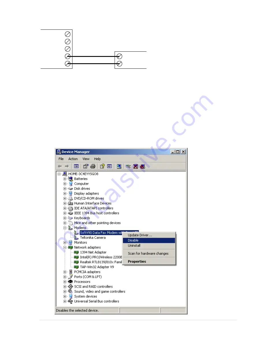
If there are any other modems in the Device Manager, disable them. 
Open  System  in  Control  Panel:  Start  =>  Settings  =>  Control  Panel  =>  System.  In  the 

Hardware  tab  select  Device  Manager  and  select  "View  >  Devices  by  Type",  then  expand 

Modem group. 
Right click on the modem which name is NOT “Teltonika Camera” and click Disable. 


Summary of Contents for MVC100

Page 1: ...TELTONIKA EDGE camera MVC100 User s Manual 1 11 ...

Page 2: ... their respective owners ATTENTION Do not disassemble the EDGE Camera equipment Do not touch the equipment if it is broken or its connecting wires are without isolation All wireless devices for data transferring may be susceptible to interference which could affect performance The device is not water resistant Keep it dry The device requires high 230V AC voltage Only qualified personnel may instal...

Page 3: ...ED Infrared LED ISP Internet Service Provider JPEG Joint Photographic Experts Group L Line LED Light Emitting Diode MPEG Motion Picture Experts Group N Neutral NiMH Nickel metal hydride OS Operating System PAP Password Authentication Protocol PC Personal computer PDP Packet Data Protocol PE Protective earth PIN Personal Identification Number PPP Point to Point Protocol QQVGA Quarter QVGA QVGA Quar...

Page 4: ...face structure 13 1 6 SETTING CAMERA S GSM CONNECTION 14 1 7 ACCESSING CAMERA FROM THE WEB 15 1 7 1 SIM card with public static IP address 15 1 7 2 SIM card with public dynamic IP address 15 2 EDGE CAMERA CONFIGURATION 16 2 1 STATUS REVIEW 16 2 1 1 Live view 16 2 1 2 Playback 17 2 2 VIDEO AND IMAGE SETTINGS 18 2 2 1 Video parameters 18 2 3 EVENT CONFIGURATION 19 2 3 1 Stream Events 19 2 3 2 On Cal...

Page 5: ...nd AC DC power adapter to which the equipment is connected shall comply with the requirements of the standard LST EN 60950 1 The equipment can be used with first Personal Computer or second Notebook computer safety class which must be properly grounded The light or attachable sensors shall comply with all safety requirements listed in LST EN 60950 1 standard Internal camera battery may be changed ...

Page 6: ... device shall have adequate breaking capacity to interrupt the maximum fault current which can flow and shall have a contact separation of at least 3 mm Turn off two pole automatic disconnect device in order to simultaneously disconnect the equipment and all with it associated equipment If the equipment has turned on battery turn it off with the switch pushing it to the position OFF ...

Page 7: ... UK plug USB cable Angled wall mount bracket Leaflet Quick Start Guide CD with software drivers and manual Note The manufacturer does not supply the SIM card which is mandatory for setting up a connection to the GSM network The SIM card may be purchased from your GSM mobile service provider Note If any of the components is missing or damaged please contact the retailer or reseller from which this ...

Page 8: ...Figure 1 EDGE camera back panel view 1 Power supply adapter socket 2 Battery ON OFF switch 3 5 pin terminal block 4 2 pin terminal block 5 MicroSD card socket 6 Power LED 7 GPRS EDGE connection status LED 8 Ready LED 9 USB socket 10 GSM antenna connector Turn on battery switch to enable backup battery The switched on battery will work as a backup power source even when the mains power fails If cam...

Page 9: ...or or for enabling infrared light source Most common used sensor examples are given in section Typical PIR and door sensor connection The Table 2 provides 5 pin terminal block description Table 2 5 pin terminal block pin out description Contact Type Description OUT 9V 12V Power output Power supply output Output voltage depends on power supply source battery NiMH 9V 250 mAh mains supply 12V 750 mA ...

Page 10: ...ith the camera into CD ROM drive of your PC The CD will start up automatically opening installation window If the window does not appear run setup exe file located in the CD Follow the instructions to install drivers and software for the MVC100 Step 1 Click Install Step 2 Click Next Step 3 Click I Agree Step 4 Click Next Step 5 Click Next Step 6 Click Ok Step 7 Click Continue Anyway Step 8 Click F...

Page 11: ...se Install the software automatically Recommended and to keep clicking Next till the installation is finished 1 4 2 Connecting to the EDGE Camera with Camera Connection Tool CCT 1 Unplug camera power supply and USB 2 Connect power supply to the camera then connect camera to the USB 3 Wait for power and ready LEDs to lights up 4 Start CCT Camera Connection Tool To start it go to Start Programs Telt...

Page 12: ...mera from the PC connect the other camera to the PC and make connection using CCT again If any problem with the connection occurs close the CCT unplug the camera from the PC USB port then connect the camera to the PC and make connection using CCT again If the problem persists close CCT open Start Control Panel System Hardware Device Manager expand Modems right click on Teltonika Camera and uninsta...

Page 13: ...structure The welcome page of the Web management interface is displayed after successful login to the camera Fig 4 From this menu all essential configuration pages can be accessed Figure 4 Welcome page of the camera WEB interface Status Review Live view real time camera view Playback review stored videos or snapshot pictures Video and image settings Video parameters adjust contrast and brightness ...

Page 14: ...quire password leave it blank 6 DNS server 1 If GSM operator does not require DNS server 1 leave it blank 7 DNS server 2 If GSM operator does not require DNS server 2 leave it blank Note from DNS servers section drop down menu choose option Custom in order to set DNS servers Do not forget to remove SIM card PIN code request Otherwise you will not be able to connect to GSM network After all the con...

Page 15: ... dynamic public IP address the IP address is given for a limited period of time which is usually no more than a few hours then the IP address is changed As the IP address is continuously changed it becomes a problem to connect to the camera To solve this problem Dynamic Domain Name Service DDNS may be used DDNS is a domain name service allowing to link dynamic IP addresses to static hostname To st...

Page 16: ...tus Battery status Shows battery energy status Live View settings allows setting the desired resolution quality and format refer to Fig 8 Figure 8 Live view settings Resolution Select the desired resolution of live view VGA QVGA QQVGA Quality Select display video quality Basic Medium Normal High Best Video format Displays allowable video format JPEG Live view session time is set in the section Liv...

Page 17: ... camera memory Recorded video or snapshots may be reviewed in the Playback section Refer to Figure 10 Figure 10 Choose Playback to review media stored in the camera s internal memory The stored media is grouped according to the date See Figure 10 For easer review year month day or time maybe selected to regroup the media Media type denotes the type of the record Video MPEG4 video clip Images serie...

Page 18: ...parameters may be used to get clear video display Fig 12 shows video configuration settings Figure 12 Video settings configuration Brightness Adjust the brightness value from range 127 to 127 Contrast Adjust the contrast value from range 0 to 127 Pressing Save button updates camera with new settings immediately However these settings are stored in temporary memory which is cleared after plugging o...

Page 19: ...itted data speed depends on GSM provider s network and GSM signal strength 2 3 1 1 Constant stream Constant stream allows configuring constant video sending to FTP SD card or by E mail Before enabling this feature do not forget to set parameters for FTP and E mail in the E mail FTP tab in camera web configuration page In order to receive video files by FTP and E mail do not forget to set reasonabl...

Page 20: ...d stream which was before the event It is made by continuously storing required amount of information in camera s internal memory Set the time in seconds to define how much data must be stored This function is very useful when checking to see what happened immediately before a trigger Send alert select this option to enable sending alert message Message will be sent if an event on contacts Contact...

Page 21: ...call longer then defined number of beeps to activate area listening feature Resolution Select desired resolution of the image or video clip VGA QVGA QQVGA Quality Select video quality Basic Medium Normal High Best Single shot Check the box if only single frame is needed Frame rate Set frame rate for the video stream Video format Select video format MJPG MPEG4 Video duration video clip duration 2 3...

Page 22: ... E mail and FTP tab in camera WEB configuration page Pressing Save button updates camera with new settings immediately These settings are stored in permanent memory To enable email function following settings must be configured Figure 16 E Mail settings SMTP server the domain name or the IP address of the email SMTP server Secure connection check the box to enable SSL for sending an email Contact ...

Page 23: ...d for sorting pictures according to the date No tree all files are stored to defined FTP directory One file the camera will rewrite the older picture with the newer so that only the last picture will be available for review in the FTP server Note to test the FTP function press Generate button in the Stream Events section Do not forget to enable and setup On event stream section 2 4 2 Network 2 4 2...

Page 24: ...g to link dynamic IP addresses to static hostname In order to have functional DDNS feature the SIM card with public static or dynamic address must be purchased from the GSM Internet service provider To start using this feature firstly a hostname must be registered on the DDNS server The camera is preconfigured to connect to the www dyndns com server for updating camera s IP address After creating ...

Page 25: ... duration and quantity is limited as all videos are stored in camera s internal volatile memory 2 5 2 Users management Set up users list in the Users management section There are three users classes Administrator User and Guest Users class Access rights Administrator Full access to all settings and functions Only one administrator user may be on camera User No access to camera settings May enter e...

Page 26: ...ssword 3 Select User class 4 Enter user s phone number Guest type user do not have this option 5 Enter user s E mail address Note Phone number format must be one of the following International xxx xxxxxx or xxx xxxxxx e g 370 60012345 or 370 60012345 Local xxxxxxxxx e g 60012345 Note the username must be one word without any spaces may contain alphanumeric and characters Figure 22 Entering e mail ...

Page 27: ...mail or phone number 2 5 3 Maintenance 2 5 3 1 Set the time Camera has internal engine to count the time The time may be synchronized with PC to witch camera is connected or with the external time server Fig 19 Figure 25 Time settings change window To synchronize time with the time server the time server domain or IP address and time zone must be entered Synchronization is done automatically The f...

Page 28: ... defaults settings If the administrator password is lost the following guide describes how to restore default username password or how to restore factory default settings 1 Connect the AC DC power adapter to the camera then connect camera to the USB port 2 Connect to camera using CCT tool 3 In the WEB browser type the IP address http 10 0 0 1 6541 4 Follow the instructions to restore default user ...

Page 29: ...onnected correctly 2 Check if the Ready and Power LEDs are light up If the power LED are turned off the problem is with power supply 3 If there are any other modems in the Device Manager disable them Open System in Control Panel Start Settings Control Panel System In the Hardware tab select Device Manager and select View Devices by Type then expand Modem group Right click on the modem which name i...

Page 30: ...2 Camera does not connect to GSM network 1 Check if the network parameters supplied by your operator were entered correctly 2 Check if the SIM card is inserted correctly 3 Check if the SIM card PIN number is removed ...

Page 31: ...ges on sensor activity for example PIR sensor door contact Pre alarm function ability to record video before sensor activity Possibility to stop transfer record activity on external contact EDGE 850 900 1800 1900 MHz GSM Power Class 4 2W for 850 900 bands GSM Power Class 1 1W for 1800 1900 bands EDGE class E2 27 dBm in 850 900 bands 26 dBm in 1800 1900 bands GPRS EGPRS Multi slot Class 12 4 slots ...

Page 32: ... detection GSM operator s identification GSM signal level measurement and display POWER SUPPLY Mains adapter 12V DC 1A Internal backup battery NiMH 9V 250 mAh Battery charging time 9h ELECTRICAL CHARACTERISTICS Nominal power supply voltage 12V Current consumption when idle 100 mA Current consumption when operating 250 mA ...

Page 33: ...odec is required 1 Run FFDShow setup by double clicking ffdshow_beta6_rev2527_20081219 file which is located in MPEG4 Codec FFDShow Install folder on MVC100 EDGE Camera support CD 2 Click Next Select destination location and click Next 3 Click Next Select Start menu folder and click Next 4 Click Next Select you speaker setup and click Next ...

Page 34: ...34 P a g e 5 Review Your selections and click Install and click Finish ...

Reviews: