


Telit EVK2 User Guide
1vv0300704 Rev.13- 2012/06/25
Reproduction forbidden without Telit Communications S.p.A. written authorization - All Rights Reserved
page
21 of 149
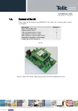
4.
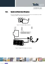
Insertion of the Interface Boards
Every
Interface Board
must be inserted on
CS1139B
paying great attention to match the
position of the main connectors; this has been made easy:
optically by a triangle drawn on both printed circuits (except CS1231X) ;
mechanically shifting a column out of regular square cross position.
Both guide systems are highlighted by orange color as shown on the next figure.
sense39b
RS232
STACKED
USB
RS232
CS1139B
SPEAKER
MECHANICAL
KEY
1
40
39
1
USB
S
O
10
1
CS1150B
OPTICAL
KEY
2
1
RESET
ON
AUDIO 2
AUDIO 1
STATUS
LED
39
40
P
L1
03
30
29
30
29
P
L1
02
S
O
10
3
1
2
2
1
2
1
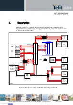
Figure 4: Positioning Guide Systems of
GM862 Interface Board
on CS1139B.
Downloaded from
Downloaded from
Downloaded from
Downloaded from
Downloaded from
Downloaded from
Downloaded from
Downloaded from
Downloaded from
Downloaded from
Downloaded from
Downloaded from
Downloaded from
Downloaded from
Downloaded from
Downloaded from
Downloaded from
Downloaded from
Downloaded from
Downloaded from
Downloaded from