LE910Cx HW User Guide
1VV0301298 Rev. 33
Page 87 of 128
2021-06-29
Not Subject to NDA
Indication of Software Ready
The SW_RDY signal provides indication on the module’s ability to receive commands. As
long as the SW_RDY is asserted low, it indicates that the LE910Cx has not finished booting
yet. Once the SW_RDY is asserted high, it indicates that the LE910Cx is ready to receive
commands.
The SW_RDY does not have a dedicated pin. The SW_RDY functionality is available on
GPIO_08 pin (by default GPIO_08 functions as SW_RDY).
RTC – Real Time Clock
The RTC within the LE910Cx module does not have a dedicated RTC supply pin. The RTC
block is supplied by the VBATT supply.
If the battery is removed, the RTC is not maintained so if it is necessary to maintain an
internal RTC , VBATT must be supplied continuously.
In Power OFF mode, the average current consumption is ~25uA.
VAUX Power Output
A regulated power supply output is provided to supply small devices from the module.
This output is active when the module is ON and turns OFF when the module is shut down.
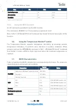
The operating range characteristics of the supply are as follows:
Item
Min
Typical
Max
Output voltage
1.75V
1.80V
1.85V
Output current
100 mA
Output bypass capacitor
(within the module)
1
μ
F
Table 40: Operating Range – VAUX Power Supply
ADC Converter
9.5.1.
Description
The LE910Cx module provides three on-board 8-bit Analog to Digital converters. Each
ADC reads the voltage level applied on the relevant pin, converts it and stores it into an
8-bit word.


