22
••••
Configuration
TX001-00-00 Rev 101 QuickSilver DV202S Video Transmitter
Using Relay Outputs
Transmitter
There are 2 onboard relay
outputs in the Transmitter that
can be used to directly drive a
device from the Receiver site.
The relay contacts are limited
to 24 DC @ 1 A maximum.
These outputs are normally
open (NO) or normally closed
(NC), but not both. The relay
outputs are located on the
terminal strip of the main board
at the left side with respect to
the back and labeled Relay 1
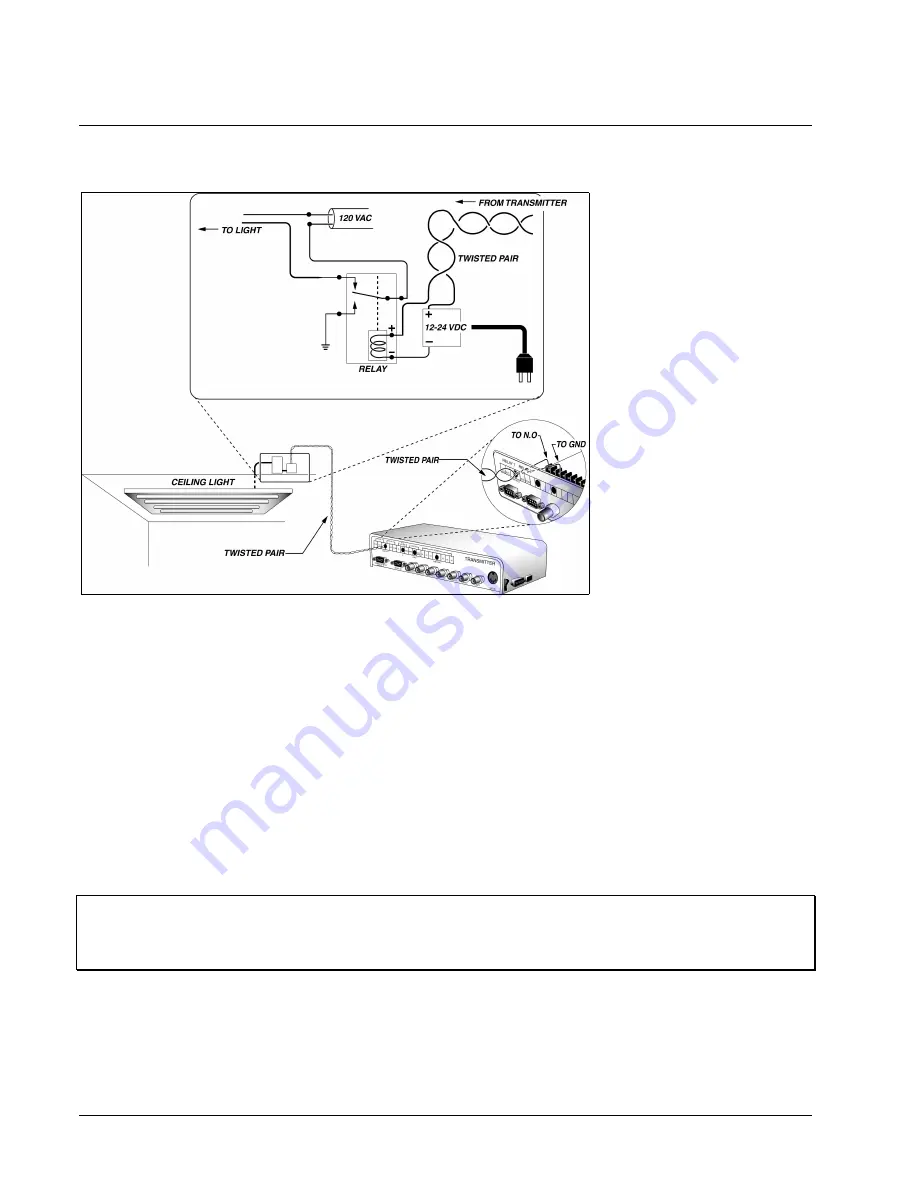
and Relay 2. Refer to Figure
27 for a typical relay setup. To
setup the relay outputs perform
the following steps.
1. Remove the 4 screws on
the sides of the
Transmitter and lift the
cover to expose the inside.
2. Route all relay cables
through the rear panel
passage holes to their
corresponding relay output
Terminal Block
connections (Relay #1 and
Relay #2).
3. Connect one color of the
cable to a common (COM) screw terminal (labeled GND on the Terminal Block).
4. Connect another color wire of the cable to the corresponding NO (NO1 or NO2) or to the NC (NC1 or
NC2) screw terminal.
5. Connect the remaining end of each cable to a suitable device. Determine whether each device has a NO
or NC input. Record each device and its type for future reference.
6. Record all wire color and relay connection associations for future reference.
Note: TeleSite recommends the use of standard practices for Alarm system companies when wiring the
relays. It is always better practice to pre-solder all connections, if required, away from the main board
and use shrink wrap tubing, in addition to tie wraps. This will ensure solid, conductive connections that
provide anchoring and suitable stress relief.
Figure 27
Typical Relay Configuration


