


Page 32 of 32
TVP Manual (full) March 2007 CE rev 03.doc
In practice this means only two relay closures are required for effective operation, system
operate and cool. If defrost is permanently linked within the interface connector the systems
automatic termination of defrost can be exploited.
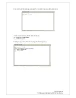
2.20 Configuration of the remote interface
The User Interface is automatically enabled when pin 9 is connected to system GND (pin 24);
this link is installed in the supplied connector.
When the connector is inserted, the system switches to REMOTE - indicated on the top, left of
the LCD display. In REMOTE only the “SCROLL” key functions, but all the indicators continue
to function (i.e. COOL, DEFROST, STANDBY) along with the RS232 read commands (includes
logging).
The system can only be taken out of remote by either removing the connector or by selecting
RS232 control via the serial link.
All the remote indicators function at all times regardless of system status. i.e. The system can
be in LOCAL or RS232.
2.21 Digital Inputs
The digital inputs accept an input voltage with a digital threshold at ~2.5 volts. The inputs are
protected against overload over a range from –48 to +48 volts. These inputs are useful for
detecting contact closures or sensing devices with open collector transistor outputs, logic level
outputs can also be detected as long as they are from a CMOS logic output guaranteed to
swing at least 3.5 volts.
The input has an RC circuit with a 0.2-millisecond time constant to stabilise signals, signals
faster than 5khz can be effected.
2.22 Digital Outputs
The digital outputs are fully isolated, they provide a contact closure to ground rated for up to
1A @ 24 VAC. The commons are all linked for the user to connect to ground or apply a
voltage (pins 4, 6, 17, 29) a 24 VAC source fused at 2A is provided on pins 35 & 36 to drive
external relays.
2.23 Suggested Wiring Schemes (see drawing)
Basic Interface - single coil units
Note Pin low indicates connection between operate and system ground has been made.
Connect pin 9 (remote enable), pin 1 (operate unit), pin 13 (operate defrost) to pin 2
(GND).
On power up the unit will be forced into remote by pin 9 being low, it will then see pin
1 low and turn on the compressor and start the PRE-COOL cycle. When pre-cool ends
the system enters STANDBY and seeing pin 13 low, forces a defrost cycle this will
terminate when CO reaches the Set point – the defrost cycle may only be momentary
as the CO value maybe higher than the set point.
On completion of defrost unit will enter STANDBY and is now ready to be controlled.
To COOL the coil a closure between 11 and system ground needs to be made. In dual,
while pin 11 is low, the system will remain in COOL.
Defrosting is achieved by breaking the link between 11 and ground allowing the
system to see pin 13 low it will then complete a DEFROST cycle before returning to
STANDBY.
In this basic scheme the system will always do a complete cycle, i.e. It will perform
COOL – DEFROST – STANDBY.
This can be expanded by adding a second switch between pin 13 and GND to select
Defrost, here if both switches are open the system is in STANDBY, to select COOL
close pin 11 to GND. To select defrost close pin 13 and then open pin 11.