background image

SyriXus Series Pumps Installation and Operation Guide

Section 3  Basic Programming and Operation

3-25

EAR99 Technology Subject to Restrictions Contained on the Cover Page

If two pumps are used with the controller, the second control 

wire should be connected to terminal 2, under DIGITAL INPUT.

If three pumps are used with the controller, the third control 

wire should be connected to terminal 3, under DIGITAL INPUT.

If four pumps are used with the controller, the fourth control 

wire should be connected to terminal 4, under DIGITAL INPUT.

NOTE

For the 4-20ma option, the negative current wire is connected to
DIGITAL GROUND and the positive should be connected to DIGI-
TAL INPUT 

3.14 Analog Flow Rate 

and Volume 

Output Options

The analog output option provides for analog monitoring of the

syringe pump flow rate. If two or less pump modules are connected to

the controller, pump volume delivered can also be monitored via

analog output. These outputs are often used with analog based plant

or process monitoring equipment.

3.14.1 Voltage Analog 

Output

Output voltage for pressure is located on the back panel of the pump

module via standard banana jacks. Refer to Figure 1-6.
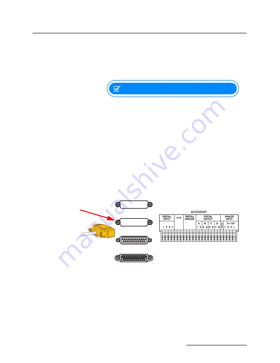
If the analog output board is installed at the factory, the output con-

nection is the female 25-pin Sub-D connector located on the rear panel

of the controller, under the 4-20mA Output label. Refer to Figure 1-5.

Figure 3-14 Analog voltage output connection, rear panel

Voltage analog outputs are pre-installed at the factory. This option has

a total of four outputs for monitoring flow rate with selectable ranges

from 0 to 5V, -5 to +5V, and 0 to 10V. The default range at installation

is 0 to 10V. Each output can be set to a different range.
The top of the selected range is the same maximum value entered for

MAX


FLOW

 when setting 

LIMITS

, as described in Section 3.8.7 "LIMITS"

of this manual. For example: if the output range is 5V and the pre-

ferred output scale is 1 volt per 10 mL/min, 

MAX


FLOW

 is set at

50 mL/min. 

MAX


FLOW

 cannot exceed the pump specification.

Controller rear panel

25-pin cable

DIGITAL I/O

4-20mA OUTPUT

USB / ETHERNET

RS-232 / RS-485

This Output can be one

of the Following:
4-20mA OUTPUT

ANALOG OUTPUT

ELECTRIC VALVES

12-CH OUTPUT

Summary of Contents for SyriXus 1000x

Page 1: ...Operation Guide Part 69 1263 358 Copyright 2022 All rights reserved Teledyne ISCO Rev April 2022 Use and Disclosure of Data Information contained herein is classified as EAR99 under the U S Export Adm...

Page 2: ...ping instruc tions provided by technical support including the use of the Return Material Authorization RMA specified Be sure to include a note describing the malfunction This will aid in the prompt r...

Page 3: ...sign alerting you to dangerous voltage inside the product The exclamation point within the triangle is a warning sign alerting you to important instructions in this manual Ce symbole signale la pr sen...

Page 4: ...om someone qualified who understands both the instrument and English very well Um eine Besch digung des Ger tes oder eine Gef hrdung des Anwenders zu vermeiden ist es notwendig da dieser vollstandig d...

Page 5: ...tteelle tai k ytt j lle aiheutuvien vahinkojen v ltt miseksi on t rke ett k ytt j hallitsee englannin kielen ja englantilaiset tekniset termit tai on saanut k ytt opastuksen englantia osaavalta henkil...

Page 6: ...the Teledyne ISCO SyriXus syringe pumps ensure that proper safety precautions are followed and that adequate ventilation is always provided around the pump The Teledyne ISCO SyriXus syringe pumps use...

Page 7: ...r cautions de s curit sont prises et qu une ventilation ad quate est toujours assur e autour de la pompe Les pompes seringues de la s rie SyriXus Teledyne ISCO utilisent des moteurs charbon Des modi f...

Page 8: ...s methane under high pressure conditions can present a hazard With concern for the safety of our customers we have designed our equipment to be as safe as pos sible However we do not recommend the use...

Page 9: ...uids associated with this instrument may be classified as car cinogenic biohazardous flammable or radioactive Should these liquids be used it is highly recommended that this application be accomplishe...

Page 10: ...s qui sont analys s dans cet instrument peuvent tre canc rig nes hasards biologiques inflammables ou radioactifs Si vous devez utiliser ces liquides hasardeux il est tr s recom mand que vous le faites...

Page 11: ...202 9990 25 1000x 0 137 8 bar lower seal 202 9990 23 Inlet Outlet Fittings 65x 1 4 F250C Gland 209 0164 02 1 4 F250C Collar 209 0164 03 260x Valco 1 8 Nut 209 0169 27 1 16 Nut 209 0094 07 1 8 Plug 20...

Page 12: ...Pre Assembled Tubing Assemblies for SyriXus Series Syringe Pumps x EAR99 Technology Subject to Restrictions Contained on the Cover Page Intentionally Left Blank...

Page 13: ...ransducers 2 7 2 3 Fluid Connection Accessories 2 8 2 3 1 Manual Refill Kit 2 8 2 3 2 Manual Outlet Valve Kit 2 9 2 4 Temperature and Pressure Controls 2 11 2 4 1 Temperature Control Jacket 2 11 2 4 2...

Page 14: ...o Four Separate Pumps 3 17 3 10 Operating Modes 3 18 3 10 1 Constant Flow 3 19 3 10 2 Constant Pressure 3 19 3 10 3 Dispense Mode 3 20 3 11 External Control 3 21 3 12 External Control Analog 3 21 3 12...

Page 15: ...ning Continuous Flow 5 19 Section 6 Modifier Addition 6 1 Overview 6 1 6 1 1 Example of Hardware 6 2 6 1 2 Two Independent Pumps 6 2 6 1 3 Continuous Flow System 6 3 6 1 4 Modifier Mode Setup 6 5 6 1...

Page 16: ...TEST 9 5 9 6 4 MOTOR CONTROL LIMITS 9 5 9 6 5 SERIAL TEST 9 7 9 7 Removing the Case Top 9 8 9 7 1 Controller Case Top Removal 9 8 9 7 2 Pump Case Top Removal 9 9 9 8 Test Points 9 9 9 8 1 Power Supply...

Page 17: ...nnection 2 10 2 8 System with temperature control jacket installed 2 11 2 9 Secure screws with the 1 4 hex wrench 2 13 2 10 Temperature control jacket installation 2 15 2 11 Inside the pump cylinder w...

Page 18: ...gnostic screen 9 5 9 3 Optical sensor interrupted by flag bottom sensor shown rear tower cover plate removed 9 6 9 4 Serial connection to a computer 9 7 9 5 Controller case top screws 2 of 4 shown TBD...

Page 19: ...waging Detail 4 2 5 1 Air Valve Package Numbers 5 1 5 2 Continuous Flow Technical Specifications Air Valves 5 2 5 3 ALL Dual Air SyriXus Pumps Conversion Table for A B Pump Pair and C D Pump Pair 5 6...

Page 20: ...TOC VIII EAR99 Technology Subject to Restrictions Contained on the Cover Page Intentionally Left Blank...

Page 21: ...where necessary for your convenience Optional system configurations may require additional kits and or software These additional options are described in their respective sections This manual contain...

Page 22: ...es REFILL OR DEPRESSURIZATION RATE 0 01 L min to 40 mL min at any pressure from 0 to 1379 bar PRESSURE RANGE 0 6895 to 1379 bar PRESSURE ACCURACY 0 1 of full scale at constant temperature PRESSURE REP...

Page 23: ...E 1 0 L min to 107 mL min at any pressure from 0 to 655 bar PRESSURE RANGE 0 6895 to 655 bar PRESSURE ACCURACY 0 5 of full scale at constant temperature PRESSURE REPEATABILITYd 0 5 of full scale withi...

Page 24: ...0 L min to 204 mL min at any pressure from 0 to 344 7 bar PRESSURE RANGE 0 6895 to 344 7 bar PRESSURE ACCURACY 0 5 of full scale at constant temperature PRESSURE REPEATABILITYd 0 5 of full scale with...

Page 25: ...ressure from 0 to 344 7 bar PRESSURE RANGE 0 6895 to 344 7 bar PRESSURE ACCURACY 0 5 of full scale at constant temperature PRESSURE REPEATABILITYe 0 5 of full scale within 48 hours at constant tempera...

Page 26: ...any pressure from 0 to 137 9 bar PRESSURE RANGE 0 6895 to 137 9 bar PRESSURE ACCURACY 0 5 of full scale at constant temperature PRESSURE REPEATABILITYe 0 5 of full scale within 48 hours at constant te...

Page 27: ...mL min flow rate 30 260x Flow Rate Range 0 10 20 30 40 50 60 70 80 90 100 107 110 0 25 50 75 100 125 150 175 200 225 250 275 300 325 350 375 400 425 450 475 525 550 575 600 625 650 675 500 655 Pressur...

Page 28: ...ut may be located elsewhere according to safety and convenience Programming and setup are performed using the keypad on the front panel The controller front panel is shown in Figure 1 4 and described...

Page 29: ...controller key functions 4 1 3 2 3 Table 1 6 Pump Controller Front Panel Label Figure 1 4 Connector Description 1 On Standby switch Turns instrument OFF and ON Does not disconnect power 2 Programming...

Page 30: ...tically to Constant Flow Available in Constant Flow Mode only NOTE This feature is automatic i e RAPID PRESS is pressed only once and the user does not enter a pressure although entering a target pres...

Page 31: ...ion The con trol cable from the rear panel of the third pump is attached to this con nector 3 PUMP B This connector is only used during multiple pump operation The con trol cable from the rear panel o...

Page 32: ...output and additional digital inputs and outputs ANALOG OUTPUTa Optional circuit provides flow rate and volume outputs Refer to 3 14 Analog Flow Rate and Volume Output Options ELECTRIC VALVESa Optiona...

Page 33: ...0 psi 2 Ground A black binding post banana jack providing a connection to circuit common 3 Pressure transducer The pressure transducer cable must be plugged in for the pump to operate 4 Control cable...

Page 34: ...ed on the Cover Page Figure 1 7 Pump front panel controls 1 Table 1 10 Pump Front Panel Figure 1 7 Connector Description 1 Mains power switch Disconnects power from the pump circuits for setup changes...

Page 35: ...p of the pump cylinder to the nine pin sub D PRESSURE TRANSDUCER connector on the pump rear panel Figure 1 6 Be sure to tighten the thumbscrews 2 Connect the control cable which originates from the fi...

Page 36: ...ucer cable refer to Figure 1 8 and Figure 1 9 must be plugged into the pressure transducer connector on the rear panel of the pump module for the pump to operate Table 1 11 Cable Part Numbers and Leng...

Page 37: ...nector on back of pump Caution The pressure transducer cable length is always 6 feet 1 8 m Never attempt to extend the length of this cable Figure 1 9 Connecting the pump and controller NOTE The FIRST...

Page 38: ...cord Turn the pump power switch ON Turn the controller ON STANDBY switch ON 2 The display will briefly show the software revision on the first line and the pump model s connected to the controller Fi...

Page 39: ...yed in the upper left corner of the screen 11 Press FLOW RATE A The words ENTER FLOW RATE should flash on the display Use the numeric keys to enter a flow rate of 10 mL min and press ENTER NOTE If you...

Page 40: ...C D to stop pump D or STOP a second time to stop all pumps Figure 1 13 Four pump stop menu If you encounter any problems during the preliminary checkout please contact the Teledyne ISCO Customer Serv...

Page 41: ...E When operating at flow rates at or below 500 L min it is strongly suggested that an insulating cover or temperature control jacket be installed Refer To Section 2 4 1 Temperature Control Jacket 2 2...

Page 42: ...g When installing ferrules on the tubing ensure the tubing extends beyond the ferrule to allow for proper crimping If the connection leaks re tighten fittings Push the tubing completely into the port...

Page 43: ...A less desirable alternative is to purchase a tubing cutter designed to handle steel tubing For quick fixes the tubing may also be cut by hand Caution Wear goggles to perform the following procedure T...

Page 44: ...cess tolerable lubricant such as sili cone grease on the cone tip and threads of the tubing to assist with the sealing process 3 Thread the collar onto the tubing until two or three threads near the c...

Page 45: ...shing Wash Gland A thin film of liquid wets the inside of the cylinder each time the piston travels up the cylinder The lowest flow rates are conducive to the most abrasive or corrosive pumping enviro...

Page 46: ...secondary wash gland seal During operation the unused wash gland outlet should always be uncapped and routed for either recirculation or drainage Detailed information about pumping salt solutions and...

Page 47: ...the purge connector as shown below 2 Regulate the nitrogen supply to slightly above atmospheric pres sure Figure 2 5 Purge connector installation 2 2 8 Flushing Pumps with External Transducers When c...

Page 48: ...ng 2 3 1 Manual Refill Kit The optional manual refill kit provides a high pressure two way valve that connects to the pump inlet to a fluid reservoir The kit contains all tubing and hardware necessary...

Page 49: ...00x pump screw the male adapter into the pump outlet 2 Connect the pre bent length of stainless steel tubing to the outlet port on the pump using the nut and ferrule Connect the other end to the top p...

Page 50: ...ainless steel tubing to the top port of the two way valve a For the SyriXus 260x connect the reducing union to the other end of this tubing 4 Connect the stainless steel tubing between the valve s bot...

Page 51: ...installed A temperature control jacket is very useful for SFC applications where cylinder cooling facilitates filling with fluids such as liquid CO2 The jacket can also be used with a circulating tem...

Page 52: ...y CYLINDER FULL when the piston is at the bottom of the cylin der 4 Toggle the STANDBY switch on the controller turning OFF the controller display 5 Toggle the POWER switch on the front of the pump to...

Page 53: ...sulting in leakage of the temperature control fluid Such damage is not repairable and will require cylinder replacement 11 If the wrench package was used to remove the cylinder remove the wrench packa...

Page 54: ...nds and pull the cylinder straight up and off the piston and push rod WARNING Do not slide the cylinder off the piston with the cylinder holding clamps installed Doing so may result in scratches to th...

Page 55: ...en pushing them over the threads of the cylinder Apply a small amount of soapy water or light oil to the O rings before installing the jacket to ease installation Figure 2 10 Temperature control jacke...

Page 56: ...posi tion in the previous step 4 Line the inlet and outlet cylinder cap ports up as before Rotate the jacket on the cylinder so that the jacket ports are oriented in the desired direction and lock the...

Page 57: ...pports the seal against movement within the cylinder and keeps the piston centered in the cylinder bore Figure 2 11 Inside the pump cylinder wetted materials SyriXus series syringe pumps are available...

Page 58: ...uch as LC SFC and SFE HIGH TEMPERATURE 0 689 5 bar Black PTFE graphite fiber reinforced high temperature compound 202 9091 09 202 9093 56 upper seal 202 9990 28 lower seal 202 9990 27 This seal is bes...

Page 59: ...are not explosion proof Use extreme caution when pumping hazardous fluids 3 2 General Controller Information The following information is intended to familiarize you with the con troller operation Onc...

Page 60: ...oller for certain combinations If the controller software is not able to function with the attached pump the controller will display UNKNOWN PUMP TYPE instead of the pump model When this happens use t...

Page 61: ...enus refer to Section 3 3 Main Menus through Section 3 7 Menu Four 3 2 4 Run Screens The run screen is shown once a program has been loaded and the pump is running The run screen which is determined b...

Page 62: ...refill are all options that may be selected from the keypad Value Selection The number keys are used to enter all numeric values required for pump operation When a numeric value is required a message...

Page 63: ...current state and settings appear on the display The letter of the current pump will appear in lower case in the upper left corner of the run screen NOTE When multiple pumps are connected the UNITS s...

Page 64: ...reen prompting to enter the selected refill rate 3 Enter the desired rate with the number keys and press ENTER 4 To save and exit the refill menu press D PREVIOUS Disable EnableAuto Refill The first l...

Page 65: ...system erases all programs and user settings This is a basic reset For information about performing a hard reset refer to Section 9 5 2 Hard Reset 3 4 6 Display Contrast From the menu you can adjust t...

Page 66: ...tiple Pumps One controller can control up to four pumps at once either together or independent of each other Complete information about using the MULTI PUMP feature is provided in Section 3 9 Control...

Page 67: ...gramming and Operation 3 9 EAR99 Technology Subject to Restrictions Contained on the Cover Page The number for the selected valve type will be blinking Press 1 2 or 3 to select the correct valve type...

Page 68: ...ation of how to use the diagnostic menu 3 6 3 Pressure Calibration This is a stored psi value to ensure optimal operation of the pressure transducer On most pumps this value known as the midpoint adju...

Page 69: ...sation is OFF there will be a pressure error proportional to the delivery flow rate For this reason the pressure integral is normally turned ON except for very low flow rates This feature is ON by def...

Page 70: ...mp to program Gradient Mode 1 Press RECALL and use the number keys to enter the number name of the gradient you wish to recall Press ENTER 2 If you enter a number of a gradient that does not exist the...

Page 71: ...key to set the value A message will blink on the right side of the screen prompting you to enter the selected limit 3 Enter the desired limit setpoint using the number keys 4 Press ENTER to save the v...

Page 72: ...gle to OFF DISPLAY Alarm When a limit has been exceeded this feature causes the pump to automatically beep a warning To turn OFF this function press softkey B once to toggle to OFF ALARM Shutdown When...

Page 73: ...horten the time required to stabilize the system pressure NOTE While pressurizing some working fluids such as CO2 heat will be generated because of compression work Use of a temperature con trol jacke...

Page 74: ...pumping system in Constant Flow Mode will consist of two syringe pumps and a valve package all regu lated by one controller Installation and operating instructions for this system are provided in Sect...

Page 75: ...HOLD PRESS In Constant Pressure Mode after the pump is empty if the outlet pressure rises past the setpoint the pump will restart and run the system down to the setpoint pressure This process will fu...

Page 76: ...umping operation Constant Pressure Refer to Section 3 10 2 Constant Pressure The Constant Pressure Mode is used when the application of fixed pressure throughout the pumping operation is required The...

Page 77: ...keys to enter the desired flow rate NOTE If you make an error press CLEAR ENTRY to delete one character at a time 4 Press ENTER once the desired flow rate is displayed 5 Press RUN to begin pump operat...

Page 78: ...OTE For time controlled delivery you must run the pump in standard Gra dient Mode as described in Section 4 Gradient Pumping for Pres sure Flow and Concentration Modes In order to access Dispense Mode...

Page 79: ...Two wires are required for analog control The analog common or ground wire should be connected to the GND terminal under ANALOG INPUT of the ACCESSORY connector on the controller rear panel Multiple...

Page 80: ...input 10V NOTE For the 4 20ma input option the negative output wire connects to DIGITAL GROUND The positive output wire connects to ANALOG INPUT 1 4 To determine the analog voltage range use the formu...

Page 81: ...r external control press EXTERNAL B The feature will toggle from OFF to ON To SET the external control for refill press REFILL C The feature will toggle from OFF to ON 3 12 4 Calculation Examples Flow...

Page 82: ...or RUN or low for STOP and must be high for normal operation of serial RS 232 control To enable the remote RUN STOP feature press MENU MORE A EXTERNAL 3 DIGITAL A ON Then press RUN or force the RUN ST...

Page 83: ...g equipment 3 14 1 Voltage Analog Output Output voltage for pressure is located on the back panel of the pump module via standard banana jacks Refer to Figure 1 6 If the analog output board is install...

Page 84: ...d initially contains three output cards for flow rate pressure and volume for Pump A Additional cards can be factory installed up to a total of 12 when the controller is initially purchased Refer to T...

Page 85: ...ning 3 Pump A Volume Remaining Signal Return 17 4 Pump B Flow Rate 4 Pump B Flow Rate Signal Return 18 5 Pump B Pressure 5 Pump B Pressure Signal Return 19 6 Pump B Volume Remaining 6 Pump B Volume Re...

Page 86: ...ning 16 Pump A Volume Remaining Signal Return 4 4 Pump B Flow Rate 17 Pump B Flow Rate Signal Return 5 5 Pump B Pressure 18 Pump B Pressure Signal Return 6 6 Pump B Volume Remaining 19 Pump B Volume R...

Page 87: ...e using the information in 9 3 Customer Service Department You can program the controller to increase or decrease pressure or flow during different steps within a single program by entering a spe cifi...

Page 88: ...the ferrules supplied for that pump by Teledyne ISCO Push the tubing completely into the connector and finger tighten Then tighten with a wrench to clamp the ferrules onto the tubing NOTE SyriXus ser...

Page 89: ...nection slightly If the leak persists swage the connection again with a new ferrule For leak test procedures refer to Technical Bulletin TB05 Field Verification Procedures 4 2 1 Inlet Connections Valv...

Page 90: ...acer block and screws pro vided 2 Connect the pre bent SST tubing between one port of the valve and the pump outlet Use the nut and ferrule to connect the tub ing at the outlet and the valve fittings...

Page 91: ...NOTE The user supplied static mixer must have a pressure rating greater than the maximum rated pressure of the pump The static mixer can be replaced by a user supplied dynamic mixer Solvents are fed f...

Page 92: ...Dual gradient system connections Inlet valves A C are from refill valve kits Figure 4 5 Dual gradient connection detail 1 8 OD X 0 069 ID SST TUBING 1 16 OD X 0 020 ID SST TUBING 1 8 OD X 0 085 ID PT...

Page 93: ...AM A 3 At the prompt enter a file number between 1 and 99 This is the file name of your program and can be the name of a new pro gram you are creating or a stored program you want to edit or run Press...

Page 94: ...of 9 999 minutes per step 9 If you want to add another step to the file program press INSERT C 10 The step number will increase by one and the default initial value will be the final value entered for...

Page 95: ...rogramming menus press PRGM GRAD then DUAL SYSTEM GRADIENT 1 and CONTINUE C The home screen will appear with FG Flow Gradient in the upper left corner 2 Press PROGRAM A 3 At the prompt enter a file nu...

Page 96: ...tes can have a resolution of 0 1 with a maximum of 9 999 minutes per step 9 If you want to add another step to the file program press INSERT C 10 The step number will increase by one and the default i...

Page 97: ...horter than the elapsed time for that step the program will proceed to the next step If the total flow rate is changed the program will immediately start using the new rate To return to the run screen...

Page 98: ...ure Flow and Concentration Modes 4 12 EAR99 Technology Subject to Restrictions Contained on the Cover Page To scroll through the four options press NEXT_ACTION A When you have reached the desired opti...

Page 99: ...he time of switchover from one pump module to the other This flow irregularity can be measured as a pressure fluctuation Teledyne ISCO pressure fluctuation at switchover is 0 35 bar at system backpres...

Page 100: ...mp approaches empty the first pump gradually takes over fluid delivery allowing the second pump to refill This cycle repeats continuously until the fluid supply reservoir is empty or until the user or...

Page 101: ...1 represents the SyriXus 500x pump valve assembly the other SyriXus series pump models will be similar 1 Select the proper pump tubing for the pumps being attached to These pump tubing assemblies are...

Page 102: ...DIGITAL OUTPUT con nectors labeled A and B and the black wires on the second pair of pumps and valve assembly need to be attached to the C and D con nectors Refer to Table 5 3 ALL Dual Air SyriXus Pu...

Page 103: ...ge Figure 5 1 Controller Accessory Connector System Outlet Fluid Inlet Model Number Label on Tubing Model Identifier Valve Mount Screws Washers SyriXus 500x Shown Other Models are Similar Front View P...

Page 104: ...ftware assumes this arrangement and the pumps must be plugged into the connectors on the back of the controller corresponding to this identification The black wires on the actuator are labeled A1 A2 B...

Page 105: ...in non flammable liquefied gas applications such as CO2 Electric valves use brush type electric motors that can be an ignition source Using electric valves with flammable fluids is not rec ommended or...

Page 106: ...l This cycle repeats continuously until the fluid supply reservoir is empty or until the user or external programmed control stops the pump NOTE When working with liquefied gases the first indication...

Page 107: ...assembly A copy of this guide can also be downloaded from www teledyneisco com Figure 5 3 represents the elevated temperature SyriXus 260x pump valve assembly the other SyriXus series pump models wil...

Page 108: ...oller can operate only one valve assembly either the single valve assembly or the dual valve assembly when the electric valve option is used DANGER THE ELECTRIC VALVE OPTION USES DC SERVO MOTORS THAT...

Page 109: ...Technology Subject to Restrictions Contained on the Cover Page Figure 5 3 Electric valve installation Overhead View Outlet Motor Solvent Inlet Model Identifier Valve Mount Screws Washers Pump Tubing C...

Page 110: ...the fluid path A switch closure low signals opening of the fluid path Table 5 6 Accessory Control Digital Outputs shows the relationship between the digital output pump valve location and the fluid pa...

Page 111: ...ect any pump to display its run screen program and operation data and to make program changes Valve specification To prevent pressure fluctuation at switchover you must specify the type of valve packa...

Page 112: ...red is displayed in liters at the top right corner of the screen Refer to Figure 5 5 to reset the volume totalizer to zero The volume totalizer feature displays the sum of the volume delivered from th...

Page 113: ...Mode Figure 5 6 Keystrokes to set up constant flow 5 5 3 Constant Pressure Mode Continuous Pressure Mode is found under the multi pump options on Menu 2 Once you have accessed the multi pump options s...

Page 114: ...nother method is to pressurize the supply reservoir perhaps with a pressure pot but this involves more hardware and is typ ically cumbersome to work with 3 A typical approach is to delay the opening o...

Page 115: ...removed from the inlet tubing this feature can be readily enabled using the key strokes shown in Figure 5 8 Figure 5 8 No Check Valve Setting to ON In Figure 5 8 when the 4 key Multi Pump is pressed...

Page 116: ...between 010 and 250 for the pressure point or between 1 and 99 for the time point 3 Press the ENTER key to store your selection 4 Press the 3 key to toggle the NCV option ON or OFF The last value set...

Page 117: ...e 3 Reset total volume refer to Figure 5 5 Liquefied Gases Checklist 1 Open the valves to atmosphere by pressing ACC CTRL then selecting each valve to open 2 Zero the pressure in each pump by pressing...

Page 118: ...ge Temperature changes can cause pressure fluctuations For available temperature control options contact Teledyne ISCO For correct overpressure response shutdown must be set to ON under PUMP LIMIT opt...

Page 119: ...n be as simple as a fluid tee or more elaborate containing machined features to enhance mixing Often this mixing device is incorporated into the user s application system This section describes a poss...

Page 120: ...1 Attach one manual refill kit available from Teledyne ISCO to each of the pumps as shown 2 Attach one manual outlet kit to each of the two pumps also available from Teledyne ISCO 3 Using metal tubin...

Page 121: ...the modifier needs to be connected to the PUMP B electrical connector on the controller NOTE When working with a modifier that boils at room temperature a pressurized reservoir for the modifier fluid...

Page 122: ...to performance issues over time Typically electric valves are preferred in this arrangement as they tend to close more securely The Teledyne ISCO electric valve option described earlier is well suited...

Page 123: ...t Control Constant Pressure Mode as detailed above 2 Be sure the pumps are stopped 3 Disconnect the inlet tubing from the inlet valve of pump A 4 Select 2 pump Independent Control Constant Pressure Mo...

Page 124: ...operate in Constant Pressure Mode and will flow up to their maximum rate to maintain the set pressure When Modifier Addition Mode is selected and RUN is pressed pump A pressure is ramped at its maxim...

Page 125: ...option on the main menu and designate the percent of modifier found under pump on the run screen to be added If your modifier boils at 3 5 bar at room temperature you may want to increase the minimum...

Page 126: ...um pressure using the numeric keypad and press ENTER to store the value Then press D PREVIOUS to return to the limits menu 4 If you need to change the minimum pressure limit press 2 MIN Enter the desi...

Page 127: ...k to the source refer to Section 6 3 2 Refill Pump B the Modifier Pump 6 3 1 Refill the CO2 Pump 1 Press STOP 2 Close the outlet valves of both pumps 3 Press REFILL and press A to designate pump A 4 A...

Page 128: ...er 1 Return to Constant Pressure Mode by pressing D SELECT PUMP and then A 2 Place the pump in Modifier Addition Mode by pressing softkey B under the words MODIFIER The word OFF will change to ON abov...

Page 129: ...erial Line Vol 1 and Modbus Messaging on TCP IP The SyriXus series syringe pump controller supports the Modbus RTU and Modbus TCP IP protocols 7 1 1 Modbus RTU The Modbus RTU protocol implementation u...

Page 130: ...d coupler P N 149 9052 00 to connect to your Ethernet 7 1 3 Modbus Configuration Options To access the Modbus configuration settings press Table 7 1 Modbus TCP IP Protocol Pin on DB 25 Casing Ethernet...

Page 131: ...e to transmit single character t1 Used to calculate interframe and intercharacter space t1 5 t3 5 50 m sec default Table 7 4 Supported Modbus Function Codes Function Code Description 01 Read Discrete...

Page 132: ...Flow Mode 00017 16 R W 1 BIT 1 Pump D in Constant Flow Mode 00018 17 R W 1 BIT 1 Pump A Pump B in Independent Mode 00019 18 R W 1 BIT 1 Pump A Pump B in Continuous Flow Constant Flow Mode 00020 19 R...

Page 133: ...Controller in Local Operation 00048 47 R W 1 BIT 1 Controller in Remote Operation 00049 48 R W 1 BIT 1 Controller in External Operation 00050 49 R W 1 BIT 1 External Refill control enabled 00051 50 R...

Page 134: ...L OUTPUT BIT 8 LOW 00079 78 R W 1 BIT 0 Disable Dispense Mode A 1 Enable Dispense Mode A Only configure if in Constant Flow Mode 00080 79 R W 1 BIT 0 Disable Dispense Mode B 1 Enable Dispense Mode B O...

Page 135: ...lag Limit Empty 00112 111 R 1 BIT 0 Pump A not at lower flag limit 1 Pump A at lower flag limit Full 00113 112 R 1 BIT 1 Pump A is overpressure 00114 113 R 1 BIT 1 Pump A is underpressure 00115 114 R...

Page 136: ...for Pump B in Constant Pressure Mode ATM BAR kPa PSI 40005 4 R W FLOAT 2 Pressure setpoint for Pump C in Constant Pressure Mode ATM BAR kPa PSI 40007 6 R W FLOAT 2 Pressure setpoint for Pump D in Con...

Page 137: ...Minimum pressure setpoint for Pump B ATM BAR kPa PSI 40045 44 R W FLOAT 2 Minimum pressure setpoint for Pump C ATM BAR kPa PSI 40047 46 R W FLOAT 2 Minimum pressure setpoint for Pump D ATM BAR kPa PSI...

Page 138: ...iters 40091 90 R FLOAT 2 Actual pressure of Pump D ATM BAR kPa PSI 40093 92 R FLOAT 2 Actual flow rate of Pump D mL min mL hr L min L hr 40095 94 R FLOAT 2 Volume remaining in Pump D milliliters 40097...

Page 139: ...is ON milliliters 40129 128 R W FLOAT 2 Volume that Pump C will be refill to if AUTO FILL TO C is ON milliliters 40131 130 R W FLOAT 2 Volume that Pump D will be refill to if AUTO FILL TO D is ON mil...

Page 140: ...mum pressure for Pump A ATM BAR kPa PSI 40203 202 R FLOAT 2 Absolute maximum flow rate for Pump A mL min mL hr L min L hr 40205 204 R FLOAT 2 Absolute maximum refill rate for Pump A mL min mL hr L min...

Page 141: ...30 R FLOAT 2 Maximum volume for Pump D milliliters 40233 232 R FLOAT 2 PUMP TYPE A 40235 234 R FLOAT 2 PUMP TYPE B 40237 236 R FLOAT 2 PUMP TYPE C 40239 238 R FLOAT 2 PUMP TYPE D 40241 240 R FLOAT 2 S...

Page 142: ...SyriXus Series Pumps Installation and Operation Guide Section 7 Modbus Configuration 7 14 EAR99 Technology Subject to Restrictions Contained on the Cover Page Intentionally Left Blank...

Page 143: ...ms because of the large range of programming languages The toolkit contains a sample program capable of running one con troller and one to three pumps Its primary purpose is to provide an example to h...

Page 144: ...1FH are ignored except for carriage return 0DH The serial unit number and baud rate can be changed from the default values through the MENU key Select SERIAL under the menu and adjust the values using...

Page 145: ...roller will not work 8 4 Cabling for Serial Control The serial connection feature allows the SyriXus series pumps to be controlled remotely from a personal computer through a common serial connector R...

Page 146: ...s store If your computer does not offer a serial port a USB to serial adapter may work but Teledyne ISCO does not support or aid in the use or connection of these devices Figure 8 1 Serial network con...

Page 147: ...functions still exist in the controller to allow the serial control of multiple controllers Teledyne ISCO no longer offers the interconnection cables for three or more controllers and has discon tinue...

Page 148: ...Teledyne ISCO cannot provide sup port or programming assistance for user developed control systems 8 6 Controller Setup Once the system is properly connected turn the pump s controller s and computer...

Page 149: ...software to control the SyriXus series pumps you must follow the DASNET communications protocol This protocol allows a number of instruments to be controlled from a single RS 232 C serial port Up to s...

Page 150: ...to DASNET communications protocol sends them to the serial port and waits for a serial response Detailed information about the Universal Driver is available at www teledyneisco com in Technical Bullet...

Page 151: ...L LEN I GET LENGTH OF INPUT STRING 10115 REM IF INPUT IS JUST R ADD SPACE AND JMP BY CHAR 10120 IF I R THEN I I GOTO 10180 10130 O O R ADD R TO OUTPUT STRING 10140 Y HEX IL GET OF CHAR IN INPUT STRING...

Page 152: ...CAPS n r while 1 cputs n rENTER STRING Q TO QUIT cgets in if in 2 Q break conv_das in 2 out convert string cputs nDASNET FORMATTED OUTPUT puts out output converted string comm_putc 0x0d send CR to se...

Page 153: ...as char char void dgets char void dputs char void comm_putc char int comm_getc void BOOL GetCTS void char unitnum HANDLE hCom DCB dcbSerialParams int _tmain int argc _TCHAR argv console appication int...

Page 154: ...ut 0x00 else sprintf_s out 255 3 3X s strlen in in for sum 0 c_ptr c_ptr sum c_ptr sum 0x100 sum 0x0FF get check sum sprintf_s c_ptr 255 2 2X sum void dgets char buffer char ptr DWORD dwBytesRead 0 pt...

Page 155: ...omPort _T COM d port hCom CreateFile szComPort GENERIC_READ GENERIC_WRITE desired access should be read write 0 COM port must be opened in non sharing mode NULL don t care about the security OPEN_EXIS...

Page 156: ...SerialParams StopBits ONESTOPBIT dcbSerialParams Parity NOPARITY if SetCommState hCom dcbSerialParams error setting serial port state printf Setting Comm port state failed Sleep 2000 exit 1 timeouts C...

Page 157: ...e a computer can function as both a network controller and a master All data transfers are in a frame format When the network controller polls an instrument it will start to respond within 200 ms If...

Page 158: ...d is eliminated if there are no messages Message field The area where the actual information is located The maximum length is 256 characters long Checksum Also a 2 digit hexadecimal number This number...

Page 159: ...nit a SyriXus model 260x pump Details on the pump message format are in Section 8 8 Serial Commands for the SyriXus Series Pumps The computer will be unit 0 and the pump controller will be unit 6 Netw...

Page 160: ...dropped from the poll In this way units 3 5 will be checked and dropped from the poll Network Controller and Master Unit 0 6R 58 CR Check for presence of unit 6 Unit 6 R 8E CR Unit 6 responds Network...

Page 161: ...dges that it accepted the command Network Controller and Master Unit 1 6R00ACONST FLOWF8 CR This puts the pump into Constant Flow Rate Mode Unit 6 R 8E CR The pump verifies that it received the messag...

Page 162: ...for percentage of modifier ALOG1 Status of the analog voltage input on pin 21 P6 ALOG2 Status of the analog voltage input on analog input 3 of the accessory connector ALOG3 Status of the analog volta...

Page 163: ...EB DISPENSEC DISPENSED Returns the dispense volume for Dispense Mode DISPENSEA DISPENSEB DISPENSEC DISPENSED Sets the dispense volume for Dispense Mode Format is XXX XXX mL Leading and trailing zeros...

Page 164: ...er final step 02 Return to initial value and hold 03 Return to initial value and repeat program LGGO Start Gradient Command This starts a gradient program same as the RUN key This command will check t...

Page 165: ...MAXPRESSA MAXPRESSB MAXPRESSC MAXPRESSD Enter to designate the maximum pressure setpoint MAXPRESSA MAXPRESSB MAXPRESSC MAXPRESSD Returns the maximum pressure setpoint MFLOWA MFLOWB MFLOWC MFLOWD Enter...

Page 166: ...Sets the pressure control input to Analog input 1 and sets the pressure range The range is 1 to 5000 the units are psi with a value of 5000 representing 5000 psi at 5 volts PRESSCNTRLDIFF2 Sets the p...

Page 167: ...the pressure setpoint STATUSA STATUSB STATUSC STATUSD Returns with status of pump May be any combination of responses listed below STATUS STOP RUN REFILL HOLD EQUIL LOCAL REMOTE EXTERNAL PROBLEM OVER...

Page 168: ...to 11 6 volts There is NO conversion of the returned number The number returned 0 to 65535 decimal will have an offset of 7500 added to the number 7500 0 volts and a scale of 5000 for every 1 volt for...

Page 169: ...e Figure 8 4 Get status string GG command R049 37510 00128 01017 06981 05743 00421 00442 00449 25046 11111000 CS Pressure Pump A Pressure Pump B Pressure Pump C ALOG1 ALOG6 Digital Inputs 1 8 Units ps...

Page 170: ...r pressure U Under pressure M Motor failure Control Status Pump A L Local control R Remote control E External control Operation Status Pump A S Pump stopped R Running F Refilling H Hold clock stopped...

Page 171: ...1 6070v Flow Rate Pump A Units Liters minute E10 Resolution 0 1nanoliter minute Volume Pump A Units Liters E9 Resolution 1nanoliter Operation Status Pump A S Pump Stopped R Running F Refilling H Holdi...

Page 172: ...ws an example of a pressure programming upload command NOTE Gradient upload commands must follow the format shown in the fig ures below Where necessary leading and trailing zeros must be included so t...

Page 173: ...xx xx FB xx xx D xxxx x File 01 99 Step Number 01 Gradient Duration Units milliliters minute Initial B Gradient Total Flow Rate Range 00 00 100 0 Final B Range 00 00 100 0 Range 0000 1 9999 0 minutes...

Page 174: ...inute Initial Gradient Percentage Gradient Total Flow Rate Range 00 00 100 0 Final Gradient Percentage Range 00 00 100 0 Range 0000 1 9999 0 minutes Range 000 0000 Maximum Flow Rate File 01 99 Step Nu...

Page 175: ...milliliters minute Initial B Gradient Total Flow Rate Range 00 00 100 0 Final B Range 00 00 100 0 Range 0000 1 9999 0 minutes Range 000 0000 Maximum Flow Rate Step Number 01 LGUL F xx S xx IB xx xx F...

Page 176: ...GE command provides scaling information for the system parameters For example 6R006RANGEA34 may return a string similar to the one shown in Figure 8 12 Figure 8 12 Range serial commands R02CP 10000 F...

Page 177: ...8 8 Serial Commands for the SyriXus Series Pumps PROBLEM INVALID COMMAND The command sent was not recognized by the pump PROBLEM INVALID OPERAND The operand character s following the sign is missing...

Page 178: ...SyriXus Series Pumps Installation and Operation Guide Section 8 Serial Interface 8 36 EAR99 Technology Subject to Restrictions Contained on the Cover Page Intentionally Left Blank...

Page 179: ...replacement components available for customer repairs Some commonly replaced parts can be ordered directly from our online store Other components will require calling our customer service department...

Page 180: ...referred to in this section first find the serial number for your unit Contact the Teledyne ISCO Customer Service Department and request a copy of the schematic for your unit You will need to provide...

Page 181: ...e box equally around the unit with resilient packing material Seal it with strapping tape and ship it to the address on the warranty The warranty at the end of the manual also describes the conditions...

Page 182: ...Reset To perform a hard reset 1 Turn the controller switch to STANDBY 2 Press and hold CLEAR ENTRY 3 While still holding CLEAR ENTRY turn the controller switch to ON Continue holding down CLEAR ENTRY...

Page 183: ...ressed Press EXIT D to return to the diagnostic menu 9 6 4 MOTOR CONTROL LIMITS Tests the digital position controls From the Limits menu you can set minimum and maximum flow rate limits and pressure l...

Page 184: ...imit will change from 0 to 1 If the cyl inder was refilled using the REFILL button it may require multiple presses of the UP 100 softkey before the Lower limit indicator changes to 0 When the Lower li...

Page 185: ...ext perform the I O test Use a null modem cable available from Teledyne ISCO P N 480 7996 00 or most computer parts stores to connect the 9 pin serial output port of a computer to the 25 pin serial RS...

Page 186: ...s easier with the controller this method of troubleshooting should be used whenever possible 9 7 1 Controller Case Top Removal Troubleshooting for a number of issues can be done on the controller main...

Page 187: ...the controller schematic and the pump schematic available at www teledyneisco com 9 8 1 Power Supply A1 Output voltages of the power supply can be verified The voltages in the pump unit between circu...

Page 188: ...two years or every 6 000 strokes whichever comes first to ensure proper service life The pump has an easy to access lube wheel that keeps the main gears lubricated during operation Refer to Figure 9 7...

Page 189: ...kept lubricated with Never seez 1 Remove the case top as detailed in Section 9 7 Removing the Case Top and front cover to gain access to all parts requiring lubrication 2 To lubricate the ball nut ru...

Page 190: ...om the transducer instead 3 Using a 1 8 Allen wrench loosen the lock screw located on the front of the cylinder mounting block about two turns Do not completely remove the lock screw Figure 9 8 Cylind...

Page 191: ...retainer Figure 9 9 from the piston and remove the seal from it Notice that the spring embedded in the seal is facing up or is on the top side of the seal 2 Clean both the piston seal retainer and th...

Page 192: ...the cylinder as described previously 2 Locate the piston Figure 9 9 3 With the exception of the 500x which has wrench flats use a spanner wrench with an 1 8 pin of appropriate size or the proper tool...

Page 193: ...7 Lock the cylinder by tightening the locking screw on the front of the cylinder mounting block to 30 in lbs 3 4 N m Reinstall cov ers 9 11 Wear Ring Cleaning and Replacement Although the wear ring do...

Page 194: ...eous solvent to another 1 Close the valve on the fluid supply tank so that no solvent is sup plied to the system 2 Turn the controller ON 3 Run the pump until the cylinder is empty It may be necessary...

Page 195: ...to fill the pump with new liquid sol vent NOTE Do not leave buffer solutions which contain dissolved salts or corro sive buffers in the cylinder overnight or for long periods of time The pump should...

Page 196: ...paratus 9 13 1 Shear Key Table 9 1 Replacement Shear Keys below provides part numbers for each pump model replacement shear key 1 Place the pump on its side and remove the four panhead screws that att...

Page 197: ...ay be easier to use a flat blade screwdriver in the shear key gap to pull the centermost half out first Take care not to push the other half into the worm gear Figure 9 12 Shear key installation tool...

Page 198: ...clockwise until the broken halves of the shear key are realigned Figure 9 11 Caution Never use tools on the ball screw Doing so will render it inoperable and beyond repair 4 Remove the castle nut and...

Page 199: ...7 Reinstall the access cover 9 14 Motor Brushes If the pump does not run properly one possible cause is worn brushes Inspect the motor brushes every two years of operation or every 6 000 piston stroke...

Page 200: ...o Restrictions Contained on the Cover Page Figure 9 13 SyriXus series motor brush replacement Figure 9 14 Location of motor brushes A new brush is 1 1 cm long Brushes should be replaced before they we...

Page 201: ...s wear down 9 14 1 Motor Brush Disassembly 1 Remove the wire lead by pulling on the spade connector 2 Unscrew the brush retainer from the motor using a straight edge screwdriver 3 Pull the old brush o...

Page 202: ...TP28 A GND 3 Connect a jumper between TP25 ANLG2 and TP28 A GND 4 Connect a jumper between TP21 ANLG1 and TP18 REF 5 Adjust R86 GAIN until the GAIN display reads 2 5000 0 0001 6 Adjust R10 OFFSET unt...

Page 203: ...install the mounts Be sure the tab portion of the mount is facing away from the sensors as shown in Figure 9 18 the screw aperture is clos est to the sensors If your pump already has the plastic tabs...

Page 204: ...n and Operation Guide Section 9 Pump Maintenance Troubleshooting and Servicing 9 26 EAR99 Technology Subject to Restrictions Contained on the Cover Page Figure 9 17 Limit sensor replacement Figure 9 1...

Page 205: ...ation is completed and the ball screw is lowered 11 Now the new limit sensors MUST be calibrated as explained in 9 15 4 Limit Sensor Calibration 9 15 4 Limit Sensor Calibration Once the new limit sens...

Page 206: ...ing in the cylinder mount ing block the cylinder will no longer turn Do not overtighten 20 Unscrew the cylinder a minimum of a half turn then line up the inlet and outlet ports as you had them before...

Page 207: ...e valve 5 Press the corresponding number key again to close the valve the motor will continue to apply torque to the valve for approxi mately 30 seconds 6 On the electric valve assembly CBA adjust the...

Page 208: ...us Series Pumps Installation and Operation Guide Section 9 Pump Maintenance Troubleshooting and Servicing 9 30 EAR99 Technology Subject to Restrictions Contained on the Cover Page Intentionally Left B...

Page 209: ...bing 2 3 D DASNET protocol 8 7 Displays setting the contrast 3 7 Drain tube 2 5 E Electrical connections 1 15 analog control 3 21 Error messages serial command 8 35 External control 3 21 analog 3 8 DA...

Page 210: ...Refill rate setting 3 5 Remote run stop 3 24 Repairs 9 3 Returning equipment 9 3 S Safety 1 i 1 viii Seals break in procedure 9 13 cleaning and replacement 9 11 Serial control cabling 8 20 commands 8...

Page 211: ...e radio frequency energy and if not installed and used in accordance with the instruction manual may cause harmful interference to radio communica tions Operation of this equipment in a residential ar...

Page 212: ...selections 3 7 3 4 Serial option menu 3 7 3 5 Total volume reset 3 8 3 6 Types of valves 3 9 3 7 Menu 3 program selections 3 10 3 8 Location of transducer midpoint value 3 10 3 9 Limits menu 3 13 3 1...

Page 213: ...e diagnostic menu 9 4 9 2 Analog input diagnostic screen 9 5 9 3 Optical sensor interrupted by flag bottom sensor shown rear tower cover plate removed 9 6 9 4 Serial connection to a computer 9 7 9 5 C...

Page 214: ...ns Connections to Female 25 Pin Sub D 3 26 3 5 Analog Output Signal Sub D Pins for 4 20mA 3 27 3 6 Analog Output Signal Sub D Pins for 0 10 VDC 3 28 4 1 Manual Refill Valve Kits 4 2 4 2 Manual Outlet...

Reviews: