


102
208528 REV M
Operations Manual, 7RU SSPA Chassis
7.2.3 Trailer Packet
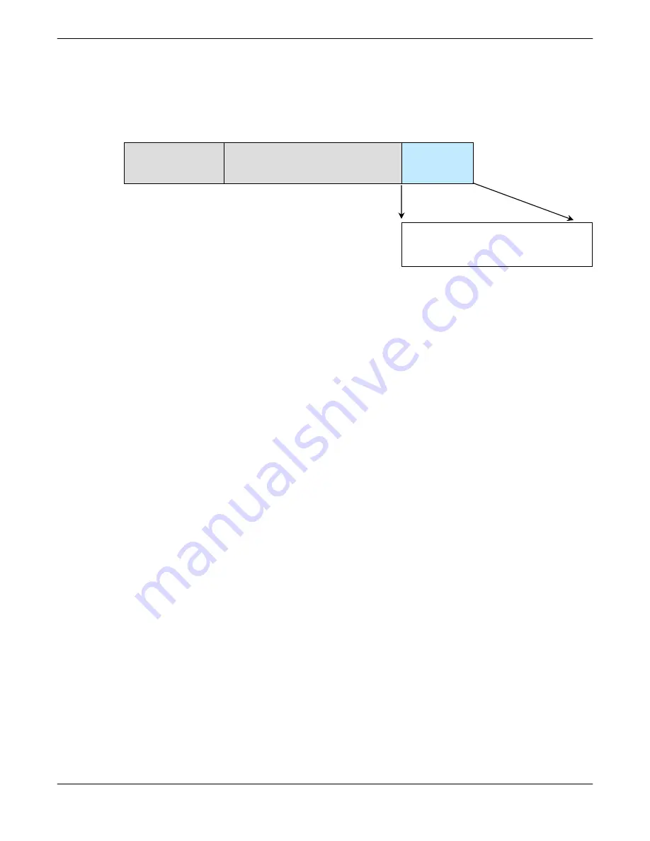
7.2.3.1 Frame Check
The trailer component contains only one (1) byte called the Frame Check Sequence, shown
in
Figure 7-6
.
This field provides a checksum during packet transmission. This value is computed as a func-
tion of the content of the destination address, source address and all Command Data Sub-
structure bytes. In general, the sender formats a message frame, calculates the check se-
quence, appends it to the frame, then transmits the packet. Upon receipt, the destination
node recalculates the check sequence and compares it to the check sequence embedded in
the frame. If the check sequences are the same, the data was transmitted without error. Oth-
erwise an error has occurred and some form of recovery should take place. In this case, the
amplifier will return a packet with the “Bad Checksum” error code set. Checksums are gener-
ated by summing the value of each byte in the packet while ignoring any carry bits. A simple
algorithm is given as:
Chksum=0
FOR byte_index=0 TO byte_index=packet_len-1
Chksum=(BYTE[byte_index])
MOD
256
NEXT
byte_index
7.2.4 Timing issues
There is no maximum specification on the inter-character spacing in messages. Bytes in mes-
sages to amplifier units may be spaced as far apart as you wish. The amplifier will respond as
soon as it has collected enough bytes to determine the message. Generally, there will be no
spacing between characters in replies generated by unites. The maximum length of the pack-
et sent to the amplifier node should not exceed 64 bytes, including checksum and frame sync
bytes. Inter-message spacing must be provided for good data transmission. The minimum
spacing should be 100 ms. This time is required for the controller to detect a “Line Cleared”
condition with half duplex communications. Maximum controller respond time is 200 ms.
HEADER
(4 bytes)
DATA
(6-32 bytes)
TRAILER
(1 byte)
Frame Check
Checksum (1 byte)
Figure 7-6: Trailer Sub-Packet
Summary of Contents for 7 RU Chassis
Page 10: ...10 208528 REV M Operations Manual 7RU SSPA Chassis THIS PAGE LEFT INTENTIONALLY BLANK...
Page 30: ...30 208528 REV M Operations Manual 7RU SSPA Chassis THIS PAGE LEFT INTENTIONALLY BLANK...
Page 78: ...78 208528 REV M Operations Manual 7RU SSPA Chassis THIS PAGE LEFT INTENTIONALLY BLANK...
Page 84: ...84 208528 REV M Operations Manual 7RU SSPA Chassis THIS PAGE LEFT INTENTIONALLY BLANK...
Page 94: ...94 208528 REV M Operations Manual 7RU SSPA Chassis THIS PAGE LEFT INTENTIONALLY BLANK...
Page 113: ...Operations Manual 7RU SSPA Chassis 208528 REV M 113 Figure 7 8 Terminal Mode Session Example...
Page 138: ...138 208528 REV M Operations Manual 7RU SSPA Chassis THIS PAGE LEFT INTENTIONALLY BLANK...
Page 144: ...144 208528 REV M Operations Manual 7RU SSPA Chassis THIS PAGE LEFT INTENTIONALLY BLANK...