Teledyne 15-0800-074 User Manual Download Page 52

Versa User Manual 


www.teledynetekmar.com
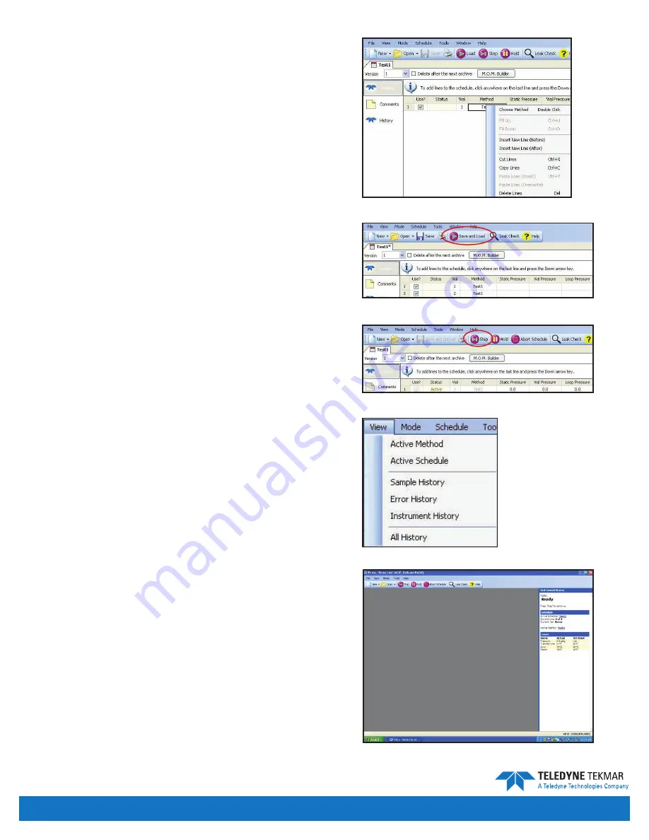
schedule editor

An existing schedule can also be edited by clicking 

file | 

open | schedule

. Browse to the folder where you store 

your schedules and open the desired schedule. 

To edit a schedule, click on the line number you wish  

to change.

To add, delete, cut, copy, or paste a line of the schedule,  

right-click with the mouse and select from the menu. 

Select the line where you want the action to occur. 

Save and Load 

Select 

save and load

 to save the method and load the 

schedule to the Versa. 

Start 

After the system has reached the set temperatures for all 

zones, click the 

step

 button to start the schedule. 

Updating an active schedule

There are a couple ways to open or view an active schedule: 

• Click 

View | active schedule

• Click the active schedule displayed in the 

Instrument 

status

 pane. 

note: 

You can make schedule changes while the Versa 

is running, but you cannot change a line of 

the schedule that is currently running, or has 

completed. Changes can only be made to the lines 

of the schedule that have not yet executed. 

Figure 4-18: Right Click Menu

Figure 4-19: Save and Load

Figure 4-20: Step Button

Figure 4-21: View Menu

Figure 4-22: Status Pane

Introduction • Page 4-9

Summary of Contents for 15-0800-074

Page 1: ...Versa User Manual www teledynetekmar com Versa Manual Part 15 0800 074 ...

Page 2: ...companies indicated own the following trademarks Teledyne Tekmar Teledyne Tekmar Teflon E I dupont deNemours Versa Teledyne Tekmar Pentium Intel Corp Upchurch Upchurch Scientific Windows XP or greater Microsoft Inc PEEK Victory PLC Co Microsoft Microsoft Inc SilcoSteel Restek Inc Document Versa Manual Part Number 15 0800 074 Rev A October 2011 Teledyne Tekmar 4763 Socialville Foster Road Mason OH ...

Page 3: ...lt of TEKMAR are not covered by this limited warranty and shall be at Buyer s expense This warranty specifically excludes the following parts supply items and mechanical wear parts such as bearings seals traps trap heaters syringes septa glassware fittings frits batteries fuses and light bulbs TEKMAR shall not be obligated to pay any costs or charges incurred by the Buyer or any other party except...

Page 4: ...l Tray 1 10 Gas Inlets and Outlets 1 10 Transfer Line 1 10 Pressure Sample Gas Inlet 1 10 Headspace Valves 1 11 Pressurization Valve 1 11 Vent Valve 1 11 Versa Heated Zones 1 11 6 Port Valve 1 11 Platen 1 11 Versa Mechanisms 1 12 Carousel Drive Assembly 1 12 Sample Elevator Mixer Assembly 1 12 Electronic Connections 1 13 Power Entry Module 1 13 USB Connection 1 13 GC IO Interface 1 13 Circuit Boar...

Page 5: ...ll Evaporation Technique 3 5 Mode Descriptions 3 7 Modes 3 7 Valves and Mechanisms 3 8 Chapter 4 versa teklinktm 2g Software Configuration 4 2 Selecting an Instrument 4 2 Configuring an Active Instrument 4 3 VOC TekLinkTM 2G Icons and Menus 4 4 File Menu 4 4 View Menu 4 4 Mode Menu 4 5 Tools Menu 4 5 Method Schedule Menus 4 6 Creating and Using Methods 4 6 Using the Method Editor 4 6 Updating an A...

Page 6: ...5 Data Versioning History and Archive 5 6 View Print System History and Error Logs 5 6 Change Justification 5 8 Chapter 6 Method Development Optimization Steps for Static Headspace Analysis 6 2 Sample Preparation 6 2 Salting Out 6 2 pH 6 2 Derivatization 6 3 Phase Ratio 6 3 Diffusion Characteristics of Solid Samples 6 3 Reverse Solvent Dilution 6 3 Sample Equilibration 6 4 Platen Sample Temperatur...

Page 7: ...s 7 8 Temperature Control Board 7 8 Master Board 7 8 GCIO Board 7 8 Elevator Motor Board 7 8 Carousel Motor Board 7 9 24V DC Board 7 9 5V DC Board 7 9 Pressure Transducer Board 7 9 General Troubleshooting 7 9 Low Response Loop 7 9 Heater Failures 7 10 How to Clean Carousel 7 10 How to Align the Sample Elevator Mixer Assembly 7 12 Returning the Versa 7 12 Unit and Parts Disposal 7 12 Teledyne Tekma...

Page 8: ...Versa User Manual www teledynetekmar com Chapter 1 Introduction ...

Page 9: ...instructions contact your Teledyne Tekmar representative for clarification Educate your personnel in the proper installation operation and maintenance of the product Only qualified personnel should install operate update program and maintain the product Install your equipment as specified in the Installation Section of this manual and according to applicable local and national codes Connect all pr...

Page 10: ...n their setpoints are above ambient temperatures Keep all instrument panels fastened when operating the Versa Use extreme care when handling hot vials particularly when unloading vials from the Versa Improper handling of hot vials may cause a burn Be alert for environmental shock or other hazards in the event that a vial would break Before cleaning up unplug the instrument and determine the nature...

Page 11: ...MM MO Original Mass Placed in the Vial MG Mass in the Gas Phase After Equilibrium MM Mass in the Matrix After Equilibrium The amount of mass that leaves the matrix for the gas phase is dictated by the partition coefficient K This is a physical constant that is directly affected by the temperature of the sample and the pressure in the vial Assuming that the make up of the matrix and the volume is c...

Page 12: ...ts of Organics From Water at 50o C Compound K Hexane 0 015 Benzene 2 5 Toluene 2 1 Xylene 1 3 Methanol 1670 Ethanol 1150 n Propanol 770 Acetaldehyde 99 Acetone 190 Methylethyl Ketone 114 Since the equilibrium is a constant Static Headspace analysis is a quantative technique The concentration in the gas phase is directly proportional to the original concentration in the matrix VG VV VM VG Volume of...

Page 13: ...ing the gas volume in the vial This will result in a denser mass or higher concentration in the gas phase for injection Sampling Once the vial has reached equilibrium the sample is ready to be prepared for injection The vial is raised onto a needle and a small amount of gas is added to the vial to pressurize it prior to sampling Once the vial is pressurized a solenoid valve is opened to allow samp...

Page 14: ...mple Mixing System allows variable power settings from low medium high Sample Pathway Siltek tubing Entire sample pathway temperature controlled up to 200 C Software TekLink 2G software in a Windows XP or greater environment via USB connnection TekLink 2G can be configured for full 21 CFR Part 11 compliance tool capability GC Interface Interfaces to virtually all commercially available GC instrume...

Page 15: ...ser Manual www teledynetekmar com This section describes and illustrates the internal and external parts of the Versa Component Overview Figure 1 2 Front of Versa Figure 1 3 Rear of Versa Introduction Page 1 8 ...

Page 16: ...as a pressure transducer that monitors the system pressure static pressure vial pressure loop pressure and leak check of the system Sample loop The Versa is equipped with a fixed volume 1mL sample loop Sample loops are available in 100 250 500µL as well as 2 3 and 5mL volumes The sample loop is filled from the sample vial via a positive pressure displacement The loop is connected to a 6 port valve...

Page 17: ...or nitrogen with a high degree of purity used to flush volatile organic analytes through the transfer line back to the GC Carrier gas enters the back of the Versa through the heated transfer line Carrier gas back flushes through the sample loop and carries volatile organic analytes over to the GC Pressure Sample Gas Inlet Pressure sample gas ultra high purity helium or nitrogen flows through the V...

Page 18: ... Versa Heated Zones The 6 Port Valve The 6 Port Valve is located inside the valve oven This valve has two positions that control the direction of sample and carrier gas flow through the headspace Platen The Platen is a heater that allows for sample equilbration at temperatures between 25 C ambient temperature and 200 C The Platen has 1 sample equilibrating at any given time Introduction Page 1 11 ...

Page 19: ... the heated Platen assembly Sample Elevator Mixer Assembly The Sample Elevator Mixer Assembly accomplishes two functions in the system It mixes the sample and raises the sample from the Carousel to the heated Platen assembly and then from the Platen back to the Carousel when the sample analysis is complete Introduction Page 1 12 Pinch Point Hazard Keep hands and other appendages away from the caro...

Page 20: ...he Versa with a GC circuit Boards The printed circuit boards provide various voltages receive and transmit signals store programs allow communication with the instrument and monitor time temperature and pressure Master Board Temperature Control Board GC IO Board Elevator Motor Board Carousel Motor Board 24V DC Power Supply 5V DC Power Supply Pressure Transducer Board Refer to circuit board picture...

Page 21: ...Versa User Manual www teledynetekmar com Chapter 2 Installation Setup ...

Page 22: ...ng the unit s weight Make sure the unit sits firmly and evenly on the surface Power Requirements After selecting and clearing a location for the Versa check the availability of the required grounded outlets The Versa uses 115V 230V power at 50 60 Hz One grounded three pronged receptacle for the main power cord The power light on the upper left front of the Versa indicates power is supplied to the ...

Page 23: ... the length 5 Make sure the gas line fittings and regulators are the correct size and type Consult your local gas supplier for the proper type and size of cylinder valves Select compatible pressure regulators based on the required valves Keep these considerations in mind Use good quality pressure regulators with stainless steel diaphragms The regulators reduce the high source pressures to the Vers...

Page 24: ...from plastic bag attached to the inside of the box 4 With two people locate the handles in the foam and lift the Versa up and out of the shipping box Remove foam from Versa unit one side at a time Confirm the unit and the contents have not sustained damage during shipment Contact shipper if damage is present DO NOT discard the packaging materials Compare the contents of the shipping carton against...

Page 25: ... Instructions for connecting a Versa to a specific model of gas chromatograph will accompany the interface cable required for your specific Versa setup USB Interface Cable In order for Versa TekLinkTM 2G to communicate with the Versa unit a USB cable connection is required Use the USB cable included in the Packing Box to make the connection betwen an available USB communications port on the PC run...

Page 26: ...fer to the GC user s manual for transfer line instructions to insure proper cutting of the carrier gas line versus the septum purge or split vent 3 A 1 16 union has been supplied in the Versa kit box and on the GC end of the Versa transfer line Use these unions and nuts and ferrules to make the following connections Place a nut and ferule on the end of the newly cut inlet line and connect to the i...

Page 27: ...e and install from there 2 If the program does not automatically start double click the Versa TekLinkTM 2G icon and follow the screen prompts The first screen that appears is the Installation Selection Screen 3 Select Versa TekLinkTM 2G and click Install this will start the Versa TekLinkTM 2G Setup Wizard 4 Click the Next button A screen appears that contains the software License Agreement Read th...

Page 28: ...efault directory is displayed below 6 Select the components you want to install from the drop down menu and click the Next button The default is displayed below 7 Select the folder in which to create the program s shortcuts and click the Next button Figure 2 5 Step 5 Figure 2 6 Step 6 Figure 2 7 Step 7 Introduction Page 2 7 ...

Page 29: ...curity and auditing button Note The CFR Install will add extra security features but limits some functionality Note Microsoft NET 2 0 or greater runtime is required for the Versa TekLinkTM 2G software to operate properly This is included with the installation of Service Pack 3 9 Click the Install button to continue with the installation or the Back button if you want to review or change any settin...

Page 30: ...tton is clicked Make your selections and click the Finish button 11 If you checked the box to launch Versa TekLinkTM 2G the program will start The Versa TekLinkTM 2G icon is in the Start All Programs Teledyne Tekmar Versa TekLink 2G program folder Also if you selected the option to place an icon on the desktop you can double click the icon to start the program Figure 2 10 Step 10 Figure 2 11 Step ...

Page 31: ...s no username and password needed in order to log in to Versa TekLinkTM 2G unless you have selected the CFR option If you have chosen the CFR option the username and password is below Username Administrator Password abc123 13 A screen appears and asks you to select an instrument to work with Versa TekLinkTM 2G Note Upon initial installation there will be no units to select Figure 2 12 Login Screen...

Page 32: ... instrument profile and releases the USB port thus allowing it to be used for another instrument 15 To specify the configuration of the unit click the Options tab From this screen the user can enable the beeper and configure the GC communication requirements as noted in the instruction sheet supplied with the GC IO cable For further information on these options please refer to the Configuring an A...

Page 33: ... have on your PC Follow the steps below that pertain to your PC s operating system If you are running Windows XP 1 When you power up the Versa the Found New Hardware Wizard will begin Choose No not this time and click Next 2 Choose Install the software automatically and click Next The Wizard will then install the new software 3 Once the install is complete click Finish to close the Wizard Figure 2...

Page 34: ...D and click Next 4 A Windows Security screen will appear Choose Install this driver software anyway The driver software will begin installing This may take a few seconds 5 Once the drivers are installed successfully close out of all windows and reboot the Versa unit After rebooting the unit and starting Versa TekLink 2G you will see a connection to the Versa Figure 2 20 Versa Main Icon Figure 2 23...

Page 35: ...Tools Configuration 1 Select the USB dropdown menu 2 Choose the available USB connection Note If you replace the Versa or add a second Versa you will need to return to the Configuration screen and select the corresponding USB connection Note If you disconnect your Versa from the USB port on your PC and then reconnect it using another USB port you will need to reinstall the USB driver and reselect ...

Page 36: ...Versa User Manual www teledynetekmar com Chapter 3 Basic Operation ...

Page 37: ...per vial preparation When a vial is undercrimped the cap shape will be concave and the cap can be easily rotated The tuck under on the vial will be at an angle not in contact with the underside of the collar If you feel some resistance when trying to rotate the cap it is probably sufficiently crimped Installation Setup Page 3 2 Figure 3 1 Properly Sealed Vial Figure 3 2 Undercrimped Vial Basic Ope...

Page 38: ... the quality of a seal Seal vial variations Amount of effort needed to make the seal Quality of the crimping tool High quality glass vials may have a tolerance of 0 2mm collar height and the seal may range in thicknesses of 2 5mm to 3 0mm Teledyne Tekmar recommends that you use an adjustable crimping tool to allow for these variations Hand or plier type crimpers accommodate varying seals and vial ...

Page 39: ...crimp head resting on the cap 5 Squeeze the crimper handles firmly in a slow and smooth motion do not squeeze quickly 6 Remove the crimper 7 Check for a proper crimp seal by lightly rotating the cap If some resistance exists it is properly sealed Spiking a Vial Spiking a vial containing a fortification solution such as an internal standard surrogate standard or stock standard can be done prior to ...

Page 40: ...se it can keep non volatile or inorganic material such as salts or polymers in the sample from entering the analytical system FET helps ensure your injection port column and detector remain as contaminant free as possible to yield the highest degree of precision accuracy and sensitivity In the FET process several microliters of a sample extract are injected into a headspace vial The vial is then h...

Page 41: ...the vial is dependent on the vial size NOTE Teledyne Tekmar vial volume is 22 3mL 0 09 RSD When preparing a vial for analysis by FET consider the following Final volume of the solvent in the vial should be 20μl Temperature of the sample platen should be approximately 10 20 degrees higher than the boiling point of the solvent used to dilute the standard Spiking a vial for FET analysis can be done b...

Page 42: ... operation Static Pressure Reading Once the needle has pierced the septa the pressure that has been generated by the sample due to the thermal exposure is measured and recorded Pressurize Gas is added to the vial to allow the vial to vent through the loop during loop fill This mode allows for a pressurization setting and a time to be set if the pressure setting is reached prior to the time the uni...

Page 43: ...al Stabilize on off A No Vial Raising Vial to Needle off off A Raising Vial to Needle Static Pressure Reading off off A Vial on Needle Pressurize on off A Vial on Needle Pressure Equilibrate off off A Vial on Needle Vial Pressure Reading off off A Vial on Needle Loop Fill off on A Vial on Needle Loop Fill Pressure Reading off on A Vial on Needle Inject on on B Lowering Vial from Needle Operating M...

Page 44: ...Versa User Manual www teledynetekmar com Chapter 4 Versa TekLink 2G ...

Page 45: ...llow the instructions below 1 Click the Add button From the Add Instrument screen shown to the right you must specify a unique name for the instrument 2 To specify the configuration of the instrument click the Options tab From this screen shown to the right the user can enable the beeper and configure the GC communication requirements as noted in the instruction sheet supplied with the GC IO cable...

Page 46: ... connects through a USB port to the user PC Deactivate This Instrument Profile Disables the instrument profile and releases the USB port thus allowing it to be used for another instrument Configuration Options Tab Enable Beeper Toggles the associated feature ON or OFF When ON the instrument uses an onboard speaker to create an audible alarm in the event of an error Gas Chromatograph GC Type specif...

Page 47: ...to a CSV file Print Prints the active window Print Preview Opens a preview of the active window printout Page Setup Opens the Page Setup screen Exit Exits Versa TekLink 2G Note This full File menu is only visible when a schedule or method is open View Menu From the View menu you can select to show the Active Method Active Schedule and the System History Logs Active Method Displays the method that ...

Page 48: ...ows the user to independently control valves mechanisms and view communication records for troubleshooting purposes Configuration Enables a user to configure optional accessories and basic instrument configurations for this specific system Leak Check Pressurizes the system and looks for a pressure decay to determine if the system is free of leaks Set System Pressure Allows the user to set the syst...

Page 49: ...ur cursor in the appropriate box beside the parameter 2 Use the number keys to change the parameter value 3 Press Enter Tab or click another cell to save the change 4 Once the method has been appropriately changed save the method by clicking File Save or the Save button in the toolbar Note Anytime a method parameter is changed an will appear beside the name until a Save or Close is performed Updat...

Page 50: ... section of the schedule the following columns are available Non editable Column Displays the line of the schedule Use A checkmark in the box indicates that line of the schedule will be run If left unchecked the line will be skipped Status Tells the status of the schedule line Aborted Active Completed Pending Preparing and Skipped Vial Denotes which position in the Versa carousel will be used Meth...

Page 51: ...o C Offset Value The increment value refers to the amount that the parameter of choice will increment during the optimization process for example a value of 10 will increment the platen sample temperature 10o C every sample The first sample will be at 40o C the next sample at 50o C and so on Increment Value Refers to how many times the analyst wishes to increment the optimization value A value of ...

Page 52: ...he schedule to the Versa Start After the system has reached the set temperatures for all zones click the Step button to start the schedule Updating an Active Schedule There are a couple ways to open or view an active schedule Click View Active Schedule Click the active schedule displayed in the Instrument Status pane Note You can make schedule changes while the Versa is running but you cannot chan...

Page 53: ...rrent field lists the current position for the corresponding component The Destination field displays a dropdown list containing valid destinations for each component The Move button causes the corresponding component to move to the position designated in the Destination field The Encoder field displays the raw encoder feedback The Home button commands the Versa to move all of the autosampler part...

Page 54: ...t the system will present a series of questions to the user The results of the Benchmark Test can be printed at the conclusion of the test and are saved in the History Log under the name entered before starting the benchmark To access a saved Benchmark Test select View All History If you only want to test a specific function you can jump to any header and begin testing History Logs The History scr...

Page 55: ...ed before the time and date selected in the text box below Clicking the down arrow will display a calendar from which the date can be selected To edit the time simply input the time desired in the text box The Omit events occurring after this date and time check box will restrict the events displayed if they have occurred after the time and date selected in the text box below Clicking the down arr...

Page 56: ...nitiate the archiving function manually This can not be performed while running a schedule If selected the Automatically Archive Data Every check box instructs the system to automatically initiate the archiving function at intervals indicated in the text box next to the check box If selected the After Archiving Remove History Items Older Than check box instructs the system to automatically remove ...

Page 57: ...u will need to follow the steps below that pertain to the operating system on your PC Installing the DFU Driver If you are running Windows XP 1 The Found New Hardware Wizard will begin Choose No not this time and click Next 2 Choose Install the software automatically and click Next The Wizard will then install the new software 3 When the install is complete click Finish to close the Wizard and reb...

Page 58: ...ick Next and the driver software will begin installing This may take a few seconds 6 Click Close once finished and reboot the Versa unit 7 Once the Versa has rebooted go to step 1 under the Upgrading Firmware section to upgrade the firmware on your system Note Once the firmware has been upgraded for the first time there is no need to reboot the unit manually during additional firmware upgrades unl...

Page 59: ...d to the event reasons selected in the menu below the check box when the check box is selected You do not need to hold shift or control to select multiple event reasons The Omit events occurring before this date and time check box will restrict the e mails generated to events that occur after the time and date selected in the text box below Clicking the down arrow will display a calendar from whic...

Page 60: ...le etc has been selected and you are ready to export from the tool bar select File Export Once the Export tab has been selected the Save As window will open Here you will use the pull down tab to select the correct pathway and file for your information Once the correct pathway and file has been selected press the Save button at the lower right hand corner to save your selection Figure 4 45 File Ex...

Page 61: ...Versa User Manual www teledynetekmar com Chapter 5 21 CFR Part 11 Compliance ...

Page 62: ...s run for the first time The user must login using the administrator s username and password and then for security reasons change the initial password 1 Type Administrator for the User Name text box Note The username and password are case sensitive 2 Type abc123 for the password 3 Click the Login button and the Change Password screen appears Change Password 1 Type abc123 for the old password 2 Cho...

Page 63: ...er is selected Connections Tab The Connections tab displays all of the connections made to the server A user with proper permissions can click the Force Disconnect button and disconnect the selected connection Setting Up User Accounts General Tab From the User Manager screen click the New User button and the New User Properties screen will appear as shown 1 Enter a Username that you wish to use th...

Page 64: ...les User can read the schedule list Connect to Instruments User can connect to instruments Create New Instrument Profiles User can add a new instrument Edit Instrument Profiles User has access to the Instrument Configuration screen Change Instrument Firmware User can update firmware View and List Instrument Profiles User can read the instrument profiles list Perform Instrument Diagnostics User has...

Page 65: ...nnection tab 3 Select the Server will wait for check box 4 Enter the number of bad attempts to allow before action is taken 5 Select the action to be taken There are two available actions Lockout the user for a set amount of time Disable the user account 6 Click OK When a user is locked out the screen to the right will appear when they try to log in When a user is disabled the screen to the right ...

Page 66: ... deleted from the current file directory if the Delete This File After Next Archive option box is selected View Print System History and Error Logs The History screen can be accessed by clicking View All History The All History log is a filterable log of all the events that have occurred in the system To adjust the event filter click the link Click here to adjust the event filter at the top of the...

Page 67: ... occurred before the time and date selected in the text box below Clicking the down arrow will display a calendar from the which the date can be selected To edit the time simply input the time desired in the text box The Omit events occurring after this date and time check box will restrict the events displayed if they have occurred after the time and date selected in the text box below Clicking t...

Page 68: ... user is initially required to give change justifications To Add Delete Change Justifications from the tool bar go to Tools and from the drop down menu select the Preferences tab A Preferences box will appear on the screen Select the Change Justifications tab If you wish to add a new Change Justification it will be necessary to type in the name of the justification you will use for future referenc...

Page 69: ...will appear with a Change Justifications tab Scroll through the justifications to insure that the addition or deletion step performed previously has taken place If it has not it is possible to Add Delete a justification at this time Note Change Justifications added or subtracted in the System Properties screen will be applied globally while it is user specific if they are changed in the Preference...

Page 70: ...Versa User Manual www teledynetekmar com Installation Setup Page 2 6 Chapter 6 Method Development ...

Page 71: ...minate an interference compound Salting Out The most commonly used Matrix Modification technique is the addition of salt to the vial Adding salt to a vial containing a liquid sample can significantly reduce Hydrogen to Hydrogen bonding making it easier for the analytes to move from the liquid phase to the gas phase An example of the Salting Out technique can be seen in the analysis of alcohols fro...

Page 72: ...os on compounds with high K values have a minimal effect It should be noted that compounds that are affected by changes in phase ratios must be measured very accurately into the vial to minimize error due to changes in the phase ratio Diffusion Characteristics of Solid Samples When dealing with solid matrices it is important to consider the diffusion of the analytes of interest from the solid samp...

Page 73: ...le Time After the platen sample temperature has been selected it is critical to select a sample equilibration time that allows the sample to reach equilibrium prior to the sampling step Allowing the sample to reach equilibrium prior to sampling allows for the method to be robust In rare cases mainly when working with solids that exhibit low diffusion characteristics the sample may never reach equi...

Page 74: ...led a static vial pressure during the sample equilibration step This pressure will normally range from between 0 5 to 11psig depending on the sample To determine the pressurization setting the static vial pressure needs to be determined Allow a minimum of three vials to equilibrate using the platen temperature and thermal exposure times that will be used to analyze samples A minimum of three sampl...

Page 75: ...re The temperature of the loop also indirectly affects the mass transferred to the column Lower valve oven temperatures result in a gas with a higher density in the sample loop prior to transfer The higher density increases the amount of analytes on column thus increasing the sensitivity Valve oven temperatures need to be selected with both sensitivity and carryover in mind Low valve oven temperat...

Page 76: ...s 0 0 0 5 minute NOTE If Platen temperatures are going to be changing throughout a schedule it is strongly advised to schedule methods to start at the lowest temperature and move to the highest temperatures The Platen heats much more quickly than it cools Therefore by ordering samples to go from lower Platen temperatures to higher temperatures a higher sample through put is achieved Inject Time Th...

Page 77: ...Versa User Manual www teledynetekmar com Chapter 7 Maintenance Troubleshooting ...

Page 78: ...k results are updated in the pop up dialog boxes The user will be required to monitor the dialog boxes for direction and guidance through the leak check procedure The leak check results are recorded in the sample history log for future reference If the system fails the leak check the user will need to isolate the system leak and correct the problem This is important in order for the system to run ...

Page 79: ... follow the steps below that pertain to the operating system on your PC Installing the DFU Driver If you are running Windows XP 1 The Found New Hardware Wizard will begin Choose No not this time and click Next 2 Choose Install the software automatically and click Next The Wizard will then install the new software 3 When the install is complete click Finish to close the Wizard and reboot the Versa ...

Page 80: ...iver software will begin installing This may take a few seconds 6 Click Close once finished and reboot the Versa unit 7 Once the Versa has rebooted go to step 1 under the Upgrading Firmware section of this instruction sheet to upgrade the firmware on your system Note Once the firmware has been upgraded for the first time there is no need to reboot the unit manually during additional firmware upgra...

Page 81: ...reventative maintenance program is the best method for maintaining your Versa Adherence to scheduled maintenance in the areas of cleaning checking of parts and lubrication will help maintain the performance standards of your unit and decrease the chances of down time The preventative maintenance schedule below lists procedures that can be performed without the assistance of a Teledyne Tekmar servi...

Page 82: ...lect Tools Benchmark Enter a name for the benchmark test and click Start Benchmark It is recommended that you print out a copy of the results for your records Transfer Line Tubing Confirm that the tubing is routed so that the potential to be snagged or crimped is limited Annual Maintenance Checks Perform Monthly Checks Lubricate the Elevator Motor Worm Gear Assembly Contact Service Representative ...

Page 83: ...the instrument the necessary time to complete the task as directed by the Benchmark Test You may stop the Benchmark Test at any time by clicking the Stop Benchmark button You can advance to any test header if you would like to test only certain functionality If you need assistance solving a problem follow these steps 1 Write down the serial number of the instrument 2 Note the type of problem you a...

Page 84: ... off and unplug the unit Check the fuses in the power module on the rear of the unit The on off switch is part of the power module Are the fuses good Replace the fuse Use correct rating and type Has the circuit breaker tripped Reset the breaker Call Teledyne Tekmar Customer Service Center 800 874 2004 Try a different power receptacle Do not use an extension cord Does unit have power Finished No No...

Page 85: ...h setting should be set to position zero GC IO Board The GC IO Board is located on the right side of the back panel The GC IO Board is responsible for GC connection communication with all valves the LED light and other boards The switch setting should be set to position zero Elevator Motor Board The Elevator Board is located on the elevator mechanism and can be seen on the left side of the unit Th...

Page 86: ... of the chassis on the left hand side The 5V DC Board is responsible for power supply to the temperature board and master board Pressure Transducer Board The Pressure Transducer Board is located in the top section of the chassis on the left hand side The Pressure Transducer Board controls the communication between the pressure transducer and Versa TekLink 2G General Troubleshooting Low Response Lo...

Page 87: ...en detected and the heater zone is unable to be controlled All temperature zones have been disabled for safety Please power down the unit and check electrical connections and relays If the problem persists contact Teledyne Tekmar s Technical Support for troubleshooting advice Open RTD Oven Platen Transfer Line The following error will appear in Versa TekLink 2G when there is an open RTD Oven Plate...

Page 88: ...he sensor as necessary This is for fine adjustments 6 Tighten one screw after adjusting the sensor 7 Rotate the carousel to home and then another position 8 Visually verify the slots of the chassis and the carousel are properly positioned 9 If more adjustment is needed loosen the tightened screw and readjust the bracket Repeat this step until everything looks centered and moves freely 10 Tighten b...

Page 89: ... are done 12 If it is not flush slightly adjust the sensor in the correct direction If you get drastically off restart from the beginning 13 Install the Sample Elevator Mixer Assembly carousel and vials back to their original position when all adjustments are completed If any problem is not resolved contact Teledyne Tekmar Customer Support Center Returning the Versa Do not return the Versa unless ...

Page 90: ...Versa User Manual www teledynetekmar com Chapter 8 Diagrams ...

Page 91: ...Versa User Manual www teledynetekmar com Detailed Plumbing Diagrams Page 8 2 ...

Page 92: ...gulator Gas 2 1 6 4 3 5 Vent Valve To GC Sample Loop Pressurize Valve Flow Restrictor Transfer Line 100ml min To Vent Restrictive Tubing Pressure Transducer A B 6 Port Valve Sample Needle Standby Ready Sample Equilibrate Mixing Stabilize Pressurize Valve On Vent Valve Off 6 Port Valve A Vial Position No Vial Diagrams Page 8 3 ...

Page 93: ...ator Gas 2 1 6 4 3 5 Vent Valve To GC Sample Loop Pressurize Valve Flow Restrictor Transfer Line 100ml min To Vent Restrictive Tubing Pressure Transducer A B 6 Port Valve Sample Needle Raising Vial to Needle Pressurize Valve Off Vent Valve Off 6 Port Valve A Vial Position No Vial Diagrams Page 8 4 ...

Page 94: ...r Gas 2 1 6 4 3 5 Vent Valve To GC Sample Loop Pressurize Valve Flow Restrictor Transfer Line 100ml min To Vent Restrictive Tubing Pressure Transducer A B 6 Port Valve Sample Needle Static Vial Pressure Reading Pressurize Valve Off Vent Valve Off 6 Port Valve A Vial Position Vial on Needle Diagrams Page 8 5 ...

Page 95: ...r Gas 2 1 6 4 3 5 Vent Valve To GC Sample Loop Pressurize Valve Flow Restrictor Transfer Line 100ml min To Vent Restrictive Tubing Pressure Transducer A B 6 Port Valve Sample Needle Pressurize Pressurize Valve On Vent Valve Off 6 Port Valve A Vial Position Vial on Needle Diagrams Page 8 6 ...

Page 96: ...r Gas 2 1 6 4 3 5 Vent Valve To GC Sample Loop Pressurize Valve Flow Restrictor Transfer Line 100ml min To Vent Restrictive Tubing Pressure Transducer A B 6 Port Valve Sample Needle Pressure Equilibrate Vial Pressure Reading Pressurize Valve Off Vent Valve Off 6 Port Valve A Vial Position Vial on Needle Diagrams Page 8 7 ...

Page 97: ...r Gas 2 1 6 4 3 5 Vent Valve To GC Sample Loop Pressurize Valve Flow Restrictor Transfer Line 100ml min To Vent Restrictive Tubing Pressure Transducer A B 6 Port Valve Sample Needle Loop Fill Loop Fill Pressure Reading Pressurize Valve Off Vent Valve On 6 Port Valve A Vial Position Vial on Needle Diagrams Page 8 8 ...

Page 98: ...lator Gas 2 1 6 4 3 5 Vent Valve To GC Sample Loop Pressurize Valve Flow Restrictor Transfer Line 100ml min To Vent Restrictive Tubing Pressure Transducer A B 6 Port Valve Sample Needle Inject Pressurize Valve On Vent Valve On 6 Port Valve B Vial Position No Vial Diagrams Page 8 9 ...

Page 99: ...3 U2_RS232_A 1 2 3 4 5 J14 U2_RS232_A BR BL GN YL POWER ENTRY MODULE 14 4383 028 1 2 3 4 PRESSURE BOARD 15 0790 090 J1 PRESSURE Transfer Line RTD 14 8790 920 115VAC 47 59 Ohms BK BK 14 8790 820 230 VAC 165 201 Ohms GN_YEL RTD 15 0810 100 120VAC 86 100 Ohms Platten Vial Platten Heater Assembly 1 GND_connection Platten EGND 15 0810 200 240VAC 346 401 Ohms RTD 15 0813 100 120VAC 129 150 Ohms Oven Via...

Page 100: ...Versa User Manual www teledynetekmar com Chapter 9 Index ...

Page 101: ...nent Overview 1 8 Configuration General Tab 4 3 Options Tab 4 3 Configuring an Active Instrument 4 3 Connecting to the Versa 2 12 Connections Tab 5 3 Creating and Using Methods 4 6 Customer Support 7 12 D Daily Maintenance Checks 7 4 Data Versioning History and Archive 5 6 Derivatization 6 3 Detailed Plumbing Diagram 8 2 Diagnostics 4 10 Diffusion Characteristics of Solid Samples 6 3 E F Edit an E...

Page 102: ...ting Environment 2 1 Optimization Steps for Static Headspace Analysis 6 2 P pH 6 2 Partition Coefficient 1 5 Permissions Tab 5 4 Phase Ratio 6 3 Platen 1 11 Platen Equilibration Time 6 7 Platen Sample Time 6 4 Platen Sample Temperature 6 4 Power Cord 2 4 Power Entry Module 1 13 Power Requirements 2 1 Preferences E mail Tab 4 16 General Tab 4 16 Pre Installation 2 1 Prepare Vials for Sampling 3 4 P...

Page 103: ... T Tools Menu 4 5 Transfer Line 1 10 Transfer Line Connections 2 5 Transfer Line Temperature 6 7 Troubleshooting 5V DC Board 7 9 24V DC Board 7 9 Carousel Motor Board 7 9 Elevator Motor Board 7 8 GC IO Board 7 8 Heater Failures 7 10 Low Response Loop 7 9 Master Board 7 8 Pressure Transducer Board 7 9 Printed Circuit Boards 7 8 Temperature Control Board 7 8 U Z Universal Gas Law Parameters 6 5 Unpa...

Reviews: