


Syringe Pump Module Installation Guide
Chapter 2: Installing the Syringe Module
12
Connecting the Syringe Module Directly to the Host PC
The syringe pump module may be controlled by a direct connection to a host
PC. The syringe pump module supports the following communications
protocols:
The USB interface is the standard configuration. A virtual COM port is
created so that the connection looks like a standard RS-232 serial port to
the host PC software.
The serial (RS-232) interface is simple and reliable, but the host computer
may lack a free serial port.
The RS-485 serial interface is provided for compatibility with certain
instruments.
Use either a serial cable or a USB cable (not both).
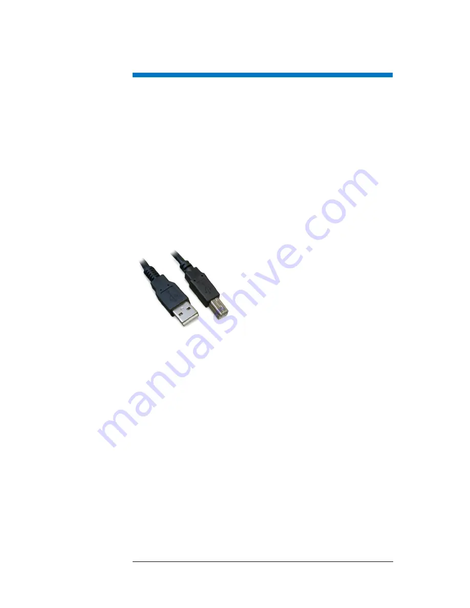
Connecting a USB Cable
You will need an “A-B” USB cable.
F
IGURE
2-9
USB Cable
1
Power on both the computer and the syringe pump module
2
Plug one end of the cable into the host computer's USB port.
3
Plug the other end into the syringe pump module’s USB port.
The computer screen should display a "New Hardware Found" window. A USB
driver must be installed to make the USB port emulate an RS-232 COM port,
and the installation must be repeated for each USB connection.
4
Allow the Windows Found New Hardware Wizard to use Windows Update to
search for a driver for the USB port.
In most cases, the driver will be found online and installed automatically. This
process may take several minutes.
If the driver is not installed automatically, insert the CD-ROM and allow the
wizard to search the CD-ROM and install the driver (the exact procedure
depends on the version of the Windows operating system). For Microsoft
Windows 7, you may need to navigate to the “FTDI Driver” folder on the CD-
ROM to find the driver file named “ftdiport.inf”. The hardware will be identified
as an “FT 232R USB UART” and then as a “USB Serial Converter.”