ONEMINI
F
IRE
A
LARM
C
ONTROL
P
ANEL
U
SER AND
I
NSTALLATION
M
ANUAL
-
R
EV
.
1.0.3
/
2018
P
AGE
26
This configuration uses lines
L+
e
L-
on pins FW+ and FW-
It is possible to connect up to 32 detectors and I/O modules.
7.6.2
Generic loop connection requirements
Match the following requirements:
Twisted and shielded 2-conductor cable,
Loop with only detectors, call points and modules, total line length should not exceed:
LENGTH
TYPE OF CABLE
Up to 1250mt
2x0.5mm
2
Up to 1850mt
2x0.75mm
2
Up to 2500mt
2x1mm
2
Up to 3500mt
2x1.5mm
2
Up to 5000mt
2x2.5mm
2
L
ine resistance should not exceed 100Ω,
Line cables installed on a dedicated path,
Cables placed at a proper distance from the power lines.
7.6.3
Open loop configuration ("T" junctions)
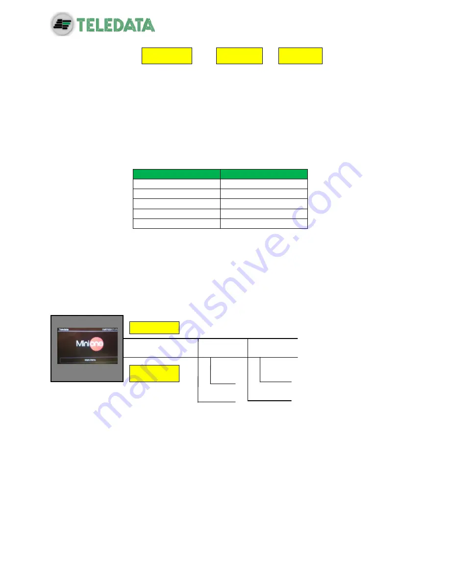
Below an example of open loop configuration with "T" junctions.
7.6.4
Open loop connection with "T" junctions connection
requirements
Match the following requirements:
The total length of all legs should not exceed the maximum allowed length, according
to the section of the cable used,
Total resistance from the control panel connectors to the end of every junction should
not exceed 100Ω.
Detector
Module
L1
– AND
L1+ AND
L1
– AND
Summary of Contents for ONEMINI
Page 1: ...ONEMINI Fire Alarm Panel User and Installation Manual ...
Page 2: ......
Page 4: ......
Page 43: ...ONEMINI FIRE ALARM CONTROL PANEL USER AND INSTALLATION MANUAL REV 1 0 3 2018 PAGE 41 ...
Page 47: ...ONEMINI FIRE ALARM CONTROL PANEL USER AND INSTALLATION MANUAL REV 1 0 3 2018 PAGE 45 ...


