ONEMINI
F
IRE
A
LARM
C
ONTROL
P
ANEL
U
SER AND
I
NSTALLATION
M
ANUAL
-
R
EV
.
1.0.3
/
2018
P
AGE
25
Follow the instructions below:
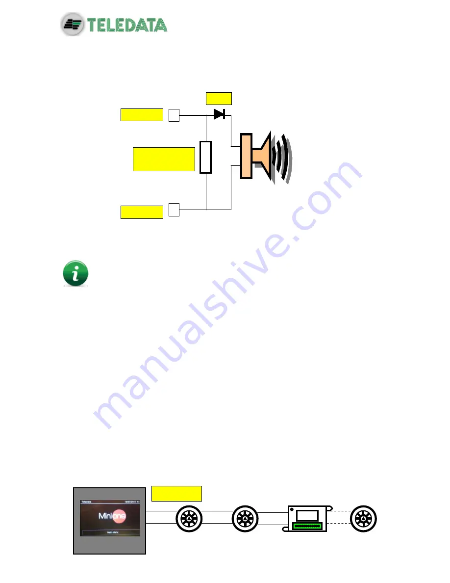
Connect a 3.3kΩ ¼ Watt end of line resistance and a 1N4007 diode. Normally these
resistors and diodes are provided with the control panel
Connect loads to the panel, use cables with a maximum resistance of 50
Ω.
The maximum current available is 1A @ 27Vdc.
The diagnostics of these outputs is activated only when the load is deactivated, that is when
the control panel does not report any alarm.
If load is used with internal protection diode, such as optical acoustic displays protected
against inversion, the protection diode may be omitted.
7.6
Communication with detectors and modules
The
ONEMINI control panel communicates with addressable detection and control devices
through a two-wire line, called loop.
It is possible to use the control panel in open loop systems or closed loop systems.
According to the effective standards, in systems where there are more than 32
modules/detectors, it is necessary to use the closed loop configuration.
7.6.1
Open loop configuration
Below an example of open loop configuration.
Dl
Pin 5/7
Pin 6/8
End of line
resistor
L1+ AND
Summary of Contents for ONEMINI
Page 1: ...ONEMINI Fire Alarm Panel User and Installation Manual ...
Page 2: ......
Page 4: ......
Page 43: ...ONEMINI FIRE ALARM CONTROL PANEL USER AND INSTALLATION MANUAL REV 1 0 3 2018 PAGE 41 ...
Page 47: ...ONEMINI FIRE ALARM CONTROL PANEL USER AND INSTALLATION MANUAL REV 1 0 3 2018 PAGE 45 ...


