background image

21

98-05141 R2

www.teejet.com

Video

Video Setup is used to set up individual cameras while using a Eight 
(8) Channel or Four (4) Channel Video Selector Module (VSM). Up to 
8 cameras can be con

fi

 gured if a VSM is installed. 

NOTE  If a VSM is not installed, VIDEO SETUP


is not available 

for selection (grayed out) .

Figure 2-32: Video Unavailable


NOTE:  Video Setup will not change the setting of a directly 

connected camera even when a VSM is on the system. 
Adjusting options will not affect a direct camera attachment.

Eight Channel VSM

When a eight (8) channel VSM is on the system, up to eight (8) 
cameras can be installed and con

fi

 gured. 

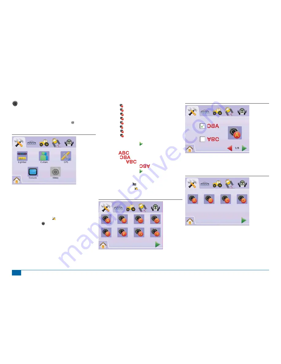
1.  Press SYSTEM SETUP TAB   
2.  Press VIDEO ICON  .

3. Select

Camera A 

A


Camera B 

B


Camera C 

C


Camera D 

D


Camera E 

E


Camera F 

F


Camera G 

G


Camera H 

H


OR
Press PAGE RIGHT ARROW   to cycle through all cameras.

4.  Select the appropriate check box(s):

Normal – 

Reverse – 

Upside Down – 

Reverse & Upside Down – 

5.  Press PAGE RIGHT ARROW   to cycle through remaining 

cameras.

6. Press

CHECKERED FLAG   to complete Video Setup.

SYSTEM SETUP TAB   to return to main System Setup 

screen.

Figure 2-33: Video w/Eight Channel VSM

Figure 2-34: Camera Configuration

8 Channel VMS w/Only A, B, C & D

If cameras are only installed in ports A, B, C and D, cameras E, F, G 
and H will not be available for con

fi

 guring.

Figure 2-35: Camera Configuration

Summary of Contents for MATRIX 570G

Page 1: ...U S E R M A N U A L E E E E E R R R R R M M M M M M A A A A A A N N N N N N U U U U U U A...

Page 2: ...le 4 The FieldPilot system will accurately follow its path and help reduce operator fatigue but it is NEVER a substitute for an alert operator The vehicle operator must be seated alert and aware of po...

Page 3: ...Section Width_______________________________________ 25 VEHICLE SETUP 25 Vehicle Type _______________________________________ 26 Antenna Height ___________________________________________ 26 Directio...

Page 4: ..._________ 40 Last Pass ________________________________________________ 40 Create Field Boundary______________________________________ 40 No Guidance Mode ________________________________________ 41 C...

Page 5: ...le ____________________________________ 56 Home Menu_____________________________________________ 56 BoomPilot ______________________________________________ 56 Guidance with SmartCable or SDM________...

Page 6: ...n PDF KML or SHP Bright daylight readable screen in either 14 5 cm 5 7 or 21 3 cm 8 4 size Product upgrades include FieldPilot Assisted Steering BoomPilot Automatic Boom Section Control Tilt Gyro Modu...

Page 7: ...gCam cameras Matrix 840G Console The Matrix 840G is designed to provide years of service under typical agricultural operating conditions A tight fitting enclosure combined with rubber covers for all c...

Page 8: ...ntenna II provides strong performance in standard operating conditions The small size of the patch antenna makes it easy to mount and unlikely to be damaged Figure 1 8 GPS Antenna FieldPilot Steering...

Page 9: ...ed on a solid structure on your vehicle the Tilt Gyro Compensation Module will intercept GPS signals from your receiver and provide corrected position data to your guidance device Diagnostic LEDs indi...

Page 10: ...nt adapters and calibrations If connecting to TeeJet consoles use speed adapter 45 20042 enter calibration 914 1000 in Europe for 8xx series in RAD mode enter calibration 9140 10000 in Europe for belo...

Page 11: ...0055 75 30056 w ClearPath Kit RAM Mount w Suction Cup 90 02349 Matrix 570G 90 02700 Matrix 840G Matrix 840G 75 30070 75 30071 w ClearPath Matrix FieldPilot BoomPilot Optional Accessory Figure 1 17 Mat...

Page 12: ...CAN to Optional RXA GPS Antenna 45 05678 Cable SMA M X SMA M 4 Pos 8 Pos Speed Cable Camera 45 05617 20 45 05618 60 Camera Extension Cable 45 05615 4 Pos 45 05765 8 Pos Speed Sense Cable 5 Pos 12V 32...

Page 13: ...een lists the module s current software version The information is also available on the About screen NOTE A firm touch is required when selecting or acknowledging a screen option Figure 1 21 Clear Jo...

Page 14: ...oles should be cleaned with mild cleaners such as glass cleaner and a soft cloth Take care not to rub dust or other abrasive materials into the touch screen surface Use a soft lint free cloth The clot...

Page 15: ...navigate The HOME BUTTON or HOME ICON gives you access to the unit s 3 functions Setup Guidance and Monitoring The 6 touch screen Menu Options Unit Setup Vehicle View Field View RealView Guidance Job...

Page 16: ...hicle Setup used to configure Vehicle Type Antenna Height Direction to Boom and Boom Offset Distance settings Tilt Gyro Module Setup used to calibrate the Tilt Gyro Module allowing for tilt correction...

Page 17: ...ure LED Spacing Display Swath Mode and LED Brightness 1 Press SYSTEM SETUP TAB 2 Press LIGHTBAR ICON 3 Select from LED Spacing sets the distance illustrated by the illuminated LEDs Display Mode determ...

Page 18: ...steering adjustment to the left Lights illuminated on the left of the Lightbar require a steering adjustment to the right Figure 2 8 Display Mode Vehicle Figure 2 9 Vehicle Lightbar Lights illuminated...

Page 19: ...n U S Metric 4 Press PAGE RIGHT ARROW to proceed to Language SYSTEM SETUP TAB to return to main System Setup screen NOTE This setting is required for FieldPilot and Tilt Sensor Operation as well as pr...

Page 20: ...ct from GPS Type select GPS source transmissions GPS Port sets D GPS COM port GPS Status displays information on GGA VTG Data Rates Num Sat HDOP PRN and Quality OR Press PAGE RIGHT ARROW to cycle thro...

Page 21: ...e 19 200 Data Bits 8 Parity None Stop Bits 1 Serial Port connection requirements Male 9 pin RS 232 serial cable NOTE May require Null modem adapter depending on pin out of receiver NMEA Strings GGA 5...

Page 22: ...sts the brightness of the console display Touch Screen Calibration used to force a touch screen calibration Screenshot allows screen images to be saved a USB drive About Save displays the system softw...

Page 23: ...time a power cycle occurs 1 Press CONSOLE ICON 2 Press CALIBRATE TOUCH SCREEN ICON 3 Press HAND ICON to enable the touch screen calibration process 4 Force touch screen calibration next time unit sta...

Page 24: ...reen calibration 7 Press PAGE RIGHT ARROW to proceed to Screenshot SYSTEM SETUP TAB to return to main System Setup screen Figure 2 25 Touch Screen Calibration Figure 2 26 Touch Screen Calibration Proc...

Page 25: ...SETUP TAB to return to main System Setup screen Figure 2 29 About Matrix 570G Figure 2 30 About Matrix 840G Save About Information To aid when troubleshooting problems in the field an end user can us...

Page 26: ...the system up to eight 8 cameras can be installed and configured 1 Press SYSTEM SETUP TAB 2 Press VIDEO ICON 3 Select Camera A A Camera B B Camera C C Camera D D Camera E E Camera F F Camera G G Came...

Page 27: ...er Module SDM is not present Configurations for Overlap Delay On Delay Off Number of Boom Sections will not be available and only one boom section width can be entered BoomPilot Setup If a SmartCable...

Page 28: ...Examples of Overlap 100 50 0 Delay On Delay On functions as a look ahead for establishing the timing for the boom section valves to switch on exactly when entering an area that has not been applied If...

Page 29: ...GE RIGHT ARROW to proceed to Boom Section Width SYSTEM SETUP TAB to return to main Boom Section Setup screen NOTE Press hold UP DOWN ARROW ICONS to quickly adjust settings NOTE A section of more than...

Page 30: ...een press icon to view available factory settings and setting ranges NOTE This setting is required for FieldPilot and Tilt Sensor Operation Figure 2 45 Single Boom Section Width No SDM Figure 2 46 Sin...

Page 31: ...enna height 3 Press PAGE RIGHT ARROW to proceed to Direction to Boom VEHICLE SETUP TAB to return to main Vehicle Setup screen NOTE This setting is required for FieldPilot and Tilt Sensor Operation as...

Page 32: ...Press TILT GYRO MODULE SETUP TAB 3 Press TILT CORRECTION ICON 4 Select On tilt correction will be applied to the GPS antenna position Off tilt correction will not be applied OR Press PAGE RIGHT ARROW...

Page 33: ...RIGHT ARROW to Tilt Calibration Complete TILT GYRO MODULE SETUP TAB to return to main Tilt Gyro Module Setup screen Figure 2 56 Level Tilt Position 2 Tilt Calibration Complete 8 Press OK ICON OK CHEC...

Page 34: ...ed correctly and is used to fine tune the oil flow Configure used to configure Coarse Adjustment Fine Adjustment Deadband and Lookahead Figure 2 59 FieldPilot FieldPilot Unavailable If a FieldPilot sy...

Page 35: ...PILOT SETUP TAB to return to main FieldPilot Setup Figure 2 64 Valve Frequency The following are common frequencies valves TeeJet Technologies Part Valve Frequency 35 02151 FP CC NP 2 hz 35 02152 FP O...

Page 36: ...ly adjust settings Figure 2 66 Minimum Duty Cycle Right Maximum Duty Cycle Maximum Duty Cycle sets the maximum speed that the wheels will steer from left to right right to left lock to lock Range is 2...

Page 37: ...will start a timer below the STOPLIGHT as well as turn the vehicle to the left 7 Press the RED STOPLIGHT when the wheels are all the way to the left The time displayed under the STOPLIGHT is the lock...

Page 38: ...n to main FieldPilot Setup NOTE Press hold PLUS MINUS ICONS to quickly adjust settings Figure 2 70 Coarse Adjustment Figure 2 71 Example of Coarse Adjustment Fine Steering Adjustment Fine Steering Adj...

Page 39: ...ckly adjust settings Figure 2 74 Deadband Figure 2 75 Example of Deadband Adjustment Lookahead Lookahead is used during Straight A B Guidance mode to adjust the vehicle s approach to the guideline Fin...

Page 40: ...B C D or E F G H can be selected to divide the screen into four separate video feeds From this screen one can enter guidance over video and steering angle modes GUIDANCE OPERATION MODES Guidance Mode...

Page 41: ...Status and Accumulated Area Figure 3 8 Guidance Bar Examples Swath acres 0 00 0 No GPS mph acres 1 35 14 4 8 9 kph ha 1 20 2 5 Mark A Accumulated Area Navigation Activity GPS Status Cross Track Error...

Page 42: ...Point Return to Point Blue Point Mark A Green Point Mark B Horizon Compass general heading can be displayed on horizon when zoomed in Coverage Area illustrates applied area and overlap Blue one applic...

Page 43: ...traight A B Guidance 1 Press the screen to activate the icons and select the GUIDANCE MODE ICON 2 Select STRAIGHT A B GUIDANCE Status Bar Icon will change to Figure 3 13 Guidance Mode Selection Swath...

Page 44: ...command and revert to the previous A B guideline when established Figure 3 18 Mark A and B Points mph acres 1 20 10 5 Mark A mph acres 2 60 10 5 Mark B The console will begin providing navigation inf...

Page 45: ...the icons and select the GUIDANCE MODE ICON 2 Select LAST PASS GUIDANCE Status Bar Icon will change to Figure 3 24 Guidance Mode Selection Swath acres 0 0 0 0 0 Last Pass 1 Drive to a desired locatio...

Page 46: ...l have no icon Figure 3 28 Guidance Off Swath acres 0 0 0 NOTE No Guidance Mode does not delete established guide lines or points from the console Clear Guidance Modes To clear all guidance points lin...

Page 47: ...The BOOMPILOT ICON is unavailable if a SmartCable or Section Driver Module SDM is not present To activate the boom a status switch must be used Only one Boom Section width will be illustrated and the...

Page 48: ...r Navigation Guidelines Mark Boundary Finish Boundary Mark Point Return to Point Cancel Boundary Cancel Point Home Menu Options or press Home Button Painted Coverage Area Figure 3 34 Overview of Field...

Page 49: ...rn Point mph acres 2 52 10 0 0 Figure 3 38 Return Point Established Swath acres 2 53 0 0 0 Distance to Established Point 1 Press the RETURN TO POINT ICON The console will begin providing the distance...

Page 50: ...tivate the icons and select the ZOOM IN OUT ICONS Zoom In will decrease the amount of map area visible Zoom Out will increase the amount of map area visible NOTE Press hold ZOOM IN OUT BUTTONS or ZOOM...

Page 51: ...TON or press the screen to activate the icons and select HOME ICON in bottom left corner of screen 2 Select REALVIEW GUIDANCE from Home Menu NOTE If a VSM or single camera is not installed RealView Gu...

Page 52: ...es will be visible when guidance is unavailable To activate Guidance Over Video 1 Press the screen to activate the icons and select the GUIDANCE OVER VIDEO ICON The UP DOWN ARROW ICONS are used to adj...

Page 53: ...ct HOME ICON in bottom left corner of screen Figure 3 52 Home Menu Swath acres 0 0 0 0 0 Single Camera Selection One of up to eight camera views can be activated in RealView Guidance if a Video Select...

Page 54: ...able for setup To change active a single camera view 1 Press the screen to activate the icons and select the VIDEO ICON 2 Press the desired CAMERA A B C or D to change the video view NOTE A camera C i...

Page 55: ...stalled Swath acres 0 0 0 0 0 Eight Channel VSM When a eight 8 channel VSM is on the system up to eight 8 cameras can be installed Two sets of four camera inputs A B C D or E F G H can be selected NOT...

Page 56: ...cons and select the SPLIT VIEW ICON Figure 3 63 Split View Selection A B C D Swath acres 0 0 0 0 0 Guideline Adjustment Guideline Adjustment is used to adjust the guidelines to match the camera s view...

Page 57: ...1 or Area 2 totals 1 Select JOB VIEW from Home Menu 2 Press JOB INFORMATION TAB 3 Press TRASH CAN ICON to delete the associated data 4 Okay to erase all job data Press Yes a All job data cleared conf...

Page 58: ...pplication areas on a map KML or Keyhole Markup Language is an XML grammar and file format for modeling and storing geographic features such as points lines images polygons and models for display in G...

Page 59: ...pefile is a digital vector storage format for storing geometric location and associated attribute information Figure 4 9 Save SHP Figure 4 10 ESRI Data Example Home Menu The Home Button or Home Icon g...

Page 60: ...ray BoomPilot status bar icon will be Off Manual NOTE The BOOMPILOT ICON is unavailable if a SmartCable or Section Driver Module SDM is not present To activate the boom a status switch must be used On...

Page 61: ...ter guidance over video and steering angle modes Job View Allows saving of information to a USB drive or clearing of information from unit Boom Monitoring Allows a computer generated view of active in...

Page 62: ...sed to drive the steering valve Minimum Duty Cycle Sets minimum amount of drive required to begin steering vehicle left right Maximum Duty Cycle Sets the maximum speed that the wheels will steer from...

Page 63: ...area and determines the no apply zone Boundary is established to the outside of an applied pass Grayed GPS is unavailable Finish Boundary Finalizes boundary process Boundaries can also be closed by tr...

Page 64: ...ntDUrville Mawson McMurdo Palmer Rothera South Pole Syowa Vostok Arctic Longyearbyen Asia Aden Almaty Amman Anadyr Aqtau Aqtobe Ashgabat Baghdad Bahrain Baku Bangkok Beirut Bishkek Brunei Calcutta Cho...

Page 65: ...n Tahiti Tarawa Tongatapu Truk Wake Wallis APPENDIX C FACTORY SETTINGS RANGES Unit Setup System Setup Icon Description Factory Setting Range LED Spacing 1 5 ft 0 46 m 0 04 9 8 ft 0 01 3 0 m Display Mo...

Page 66: ...IT SPECIFICATIONS Dimensions Matrix 570G 6 36 in x 5 87 in x 2 3 in 161 5 mm x 149 1 mm x 58 4 mm Matrix 840G 10 6 x 7 1 x 2 4 in 27 0 x 18 0 x 6 0 cm Weight Matrix 570G 1 75 lbs 0 794 kg Matrix 840G...

Page 67: ...nce Superimposed Over Video Guidance Only Video Only Bright Daylight Readable Screen Easy to Use 3D Graphical Guidance Coverage Mapping Data Export 98 05141 R2 TeeJet Technologies 2010 1801 Business P...

Reviews: