18
www.teejet.com
OVER
VIE
W
SE
TUP
APPENDIX
GE
TTING ST
AR
TED
OPER
ATION
ISOBUS Job Computer : IC18 Sprayer
Regulation Parameters
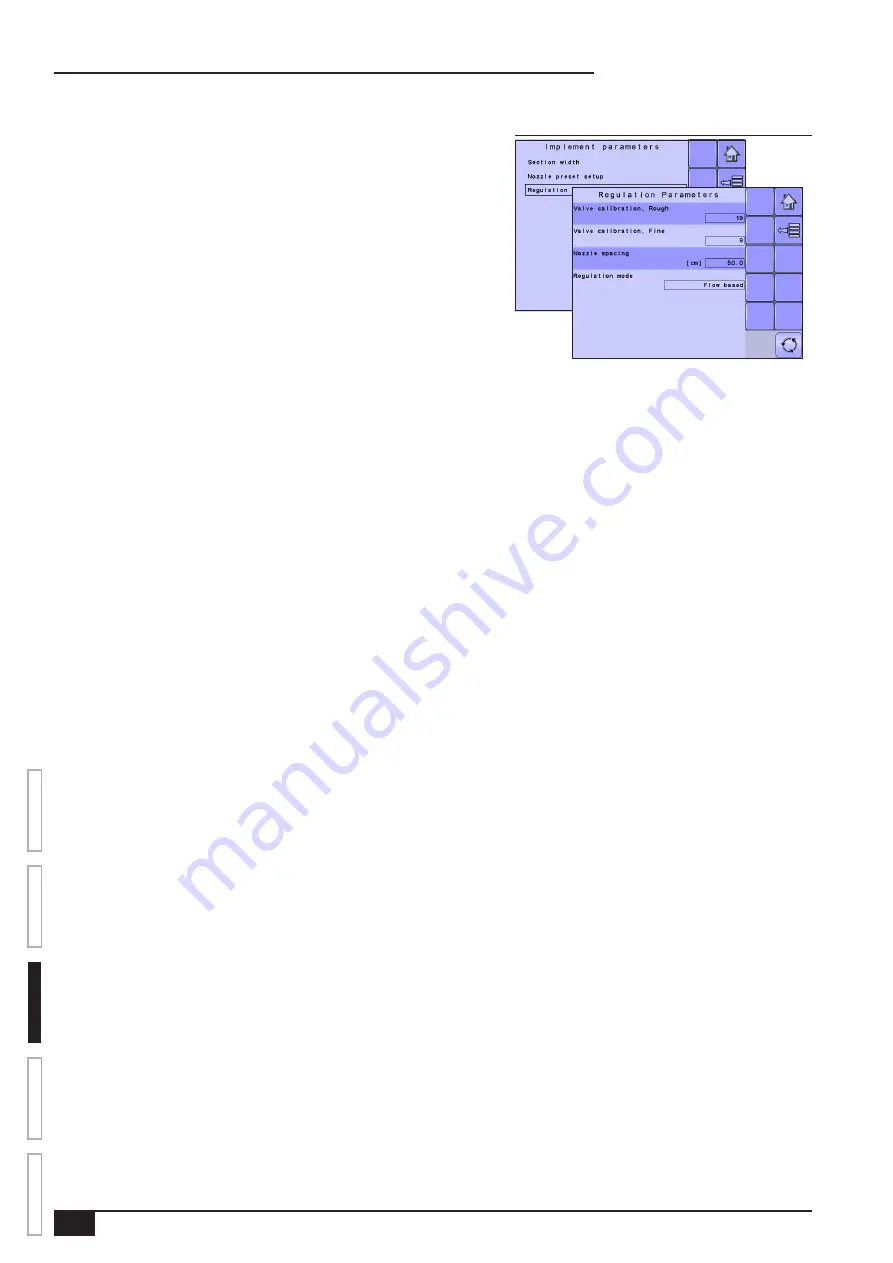
Figure 3-22: Regulation Parameters
Regulation Parameters establishes adjustments to the valve calibrations, nozzle
spacing and regulations mode.
NOTE: Adjusting the Valve Calibration settings involves significant changes and
adjustments should therefore be made in small steps.
Valve Calibration, Rough
Rough regulation value calibration allows you to regulate the setting of the
regulating valve to accommodate different application needs. Operating conditions
may necessitate a higher or lower response setting for the regulating valve. This
value adjusts the setting for coarse adjustments in relation to a large percentage
outside of the target application rate
►If the system is too slow in finding the correct rate, the values should be
increased.
►If the system is too unstable, the values should be decreased.
•
To select the Valve Calibration, Rough, use the number pad or slide bar.
If your system is plumbed in a bypass mode, the valve setting number of 9 works very well in most applications
If your system is plumbed in a throttling mode, start with a valve setting number of 3 and adjust the number according to your application
requirements. Low flow situations will require a slower response time. Adjusting agitation volumes to accommodate the regulating valve to
work in a more fully open position allows for a faster response time, with little to no searching.
NOTE: This setting value can be adjusted to optimize system performance. If you notice that the valve seems to “search” for the
programmed application rate by cycling the pressure up and down continuously, reduce the number until the “searching” is
minimized or eliminated. Conversely, a higher number will increase the valve response time and “speed up” the rate of adjustment.
Valve Calibration, Fine
Fine regulation value calibration allows you to regulate the setting of the regulating valve to accommodate different application needs.
Operating conditions may necessitate a higher or lower response setting for the regulating valve. This digit adjsuts the setting for the fine
tune adjustment in relation to a small percentage close to the target application rate.
►If the system is too slow in finding the correct rate, the values should be increased.
►If the system is too unstable, the values should be decreased.
•
To select the Valve Calibration, Fine, use the number pad or slide bar.
If your system is plumbed in a bypass mode, the valve setting number of 5 works very well in most applications.
If your system is plumbed in a throttling mode, start with a valve setting number of 3 and adjust the number according to your application
requirements. Low flow situations will require a slower response time. Adjusting agitation volumes to accommodate the regulating valve to
work in a more fully open position allows for a faster response time, with little to no searching.
NOTE: This setting value can be adjusted to optimize system performance. If you notice that the valve seems to “search” for the
programmed application rate by cycling the pressure up and down continuously, reduce the number until the “searching” is
minimized or eliminated. Conversely, a higher number will increase the valve response time and “speed up” the rate of adjustment.
Nozzle Spacing
Nozzle Spacing establishes the distance between the nozzles on the boom.
•
To select the Nozzle Spacing, use the number pad or slide bar.
Regulation Mode
Regulation Mode determines if the rate control is pressure based or flow based.
• To select the Regulation Mode, select an option from the drop down menu or use the UP/DOWN ARROWS to highlight the option.
Summary of Contents for ISOBUS IC18
Page 1: ...U S E R M A N U A L IC18 SPRAYER JOB COMPUTER Software version 1 06 ...
Page 5: ......
Page 44: ......


