


EV Inverter Operating Manual
___________________________________________________________________________
TECO
– Westinghouse Motor Company 11
Section 6
-
Peripheral Power Devices
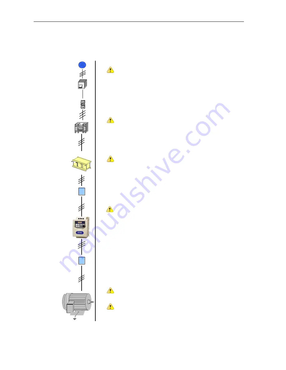
The following describes some of the precautions that should be followed when selecting peripheral power
devices.
Induction
Motor
Power Supply
Molded
Circuit
Breaker
Magnetic
Contactor
AC Reactor
Input Noise
Filter
EV
Inverter
Output
Noise Filter
Fuse
E
or
Power supply:
Make sure the correct voltage is applied to avoid damaging the
inverter.
Molded-case circuit breaker (MCCB) or fused disconnect
A molded-case circuit breaker or fused disconnect must be installed
between the AC source and the inverter that conforms to the rated voltage
and current of the inverter to control the power and protect the inverter.
(See section 7 for fuse ratings)
Do not use the circuit breaker as the run/stop switch for the
inverter.
A suitable fuse should be installed with inverter rated voltage and current
when a MCCB is not being used. (Please refer to Sec.7 for
recommended current ratings)
Ground fault detector / breaker:
Install a ground fault breaker to prevent problems caused by current
leakage and to protect personnel. Select current range up to 200mA,
and action time up to 0.1 second to prevent high frequency failure.
Magnetic contactor:
Normal operations do not need a magnetic contactor. When performing
functions such as external control and auto restart after power failure, or
when using a brake controller, install a magnetic contactor.
Do not use the magnetic contactor as the run/stop switch for
the inverter.
AC line reactor for power quality:
When inverters are supplied by a high capacity (above 600KVA) power
source, an AC reactor can be connected to improve the power factor.
Input and output noise filter:
A filter must be installed when there are inductive loads affecting the
inverter.
Inverter:
Output terminals T1, T2, and T3 are connected to U, V, and W terminals
of the motor. If the motor runs in reverse while the inverter is set to run
forward, swap any two terminals connections for T1, T2, and T3.
To avoid damaging the inverter, do not connect the input terminals
T1, T2, and T3 to AC input power.
Connect the ground terminal properly.( 230V series: Rg <100
;
460V series: Rg <10
.)
Summary of Contents for EV INVERTER Series
Page 69: ......


