Apr Finger-Card - Ver. 1.0 - 09/2011
Ver. 1.0 - 09/2011 - Apr Finger-Card
29
1.
DESCRIPTION
The
APR FINGER-CARD
is a control unit with biometric finger print and RFID card reader. The
ABS casing, designed by Pininfarina, is available in the following colors:
• Gray (item F103APRFINCAR/G)
• Black (item F103APRFINCAR/N)
• White (item F103APRFINCAR/B)
Compatibility
The finger print reader can only be connected to the listed control panels, on condition that they are
upgraded to the specified firmware release:
TP8-64 BUS
- FW rel. 2.1.00 and following
TP16-256
- FW rel. 3.1 and following
TP8-96 VIDEO
- FW rel. 0.8.01 and following
TP16-512
- FW rel. 0.8.01 and following
Tecnoalarm software
- SW rel. 4.3.9 and following.
2.
MOUNTING
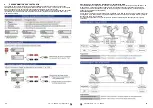
The device must be fixed to the wall, at a height which permits a comfortable use by the user.
As it is shown in the exploded drawing (fig. 1), the device is composed of three parts, the rear
panel, which is fixed on a plane surface, the electronic module and the cover. The electronic
module is hooked into the rear panel by means of a guide rail, which keeps the module in the right
postion. To remove the module from the rear panel it is enough to slightly lift the snapfit indicated in
the figure.
To close the device, hook the cover in the upper part of the rear panel (snap-fit grooves), lower it
and block it with the screw in the lower part of the casing.
3.
CONNECTION
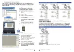
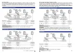
The reader must be connected to the control panel via the serial bus (fig. 2). Each device
connected via serial line must be identifiable through a unique address, i.e. each address must
correspond to only one device (fig. 3). The quantity of available addresses depends on the module
or the control panel.
The removable terminal block is connected to the bottom of the casing through a guide rail. For
wiring remove the terminal block, afterwards insert it again with caution and place the electronic
module on top of it. Special guide rails help to correctly align the terminal block and the electronic
module and ensure the electrical contact.
4.
FUNCTIONING
LED signaling
The device provides 4 signaling LED (fig.
4). L1, L2 and L3 indicate the status of the
three associated programs, L4 is an OCG
LED and signals system status.
Programs-reader association
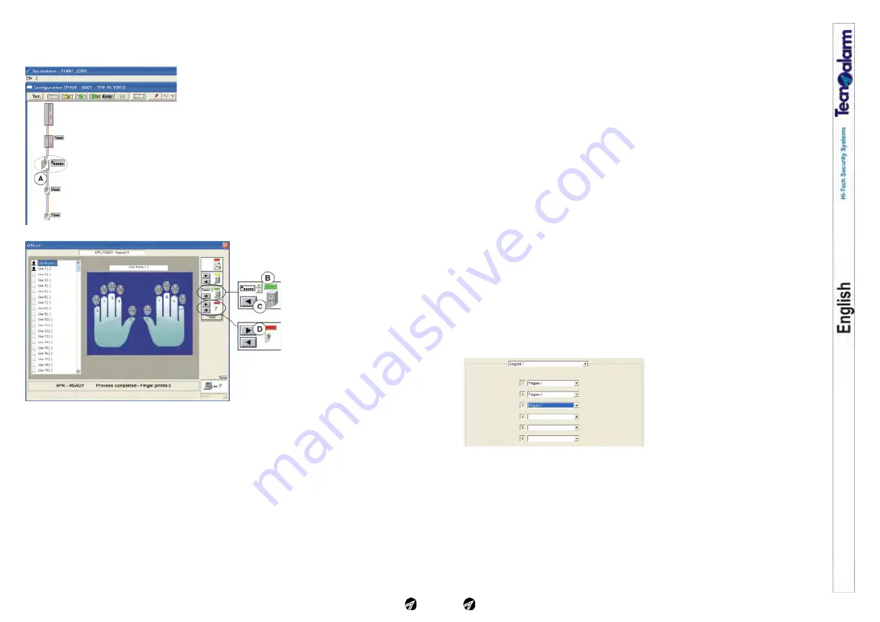
The APR FINGER-CARD reader can
manage up to three programs. The
possibilities of association of the programs
vary according to the control panel. Using
the TP8-64 BUS control panel the
association is fixed, the readers manage
only the first three programs. Using the TP8-96 VIDEO, TP16-256 and TP16-512 control panels the
association is free. It is possible to chose any 3 programs among those managed by the control
panel.
Programs-RFID cards association
While the card reader can manage only three programs, it is possible to associate the RFID card to
all of the control panel's programs, or only some of them, without any restriction.
A card, even if associated to many programs, can only arm and disarm those programs which are
associated to the reader used.
Card reading area
The antenna of the reader is mounted behind the front cover (fig. 5). To read the card it is enough
to approach it to the device from the front. The card is read at a distance of 4 to 8cm (area of
perception). In the arming or disarming phase to select the programs, several card readings may
be required. In this case, remove the card some 10cm (limit of perception) and approach it again,
as many times as necessary.
Programs-finger prints association
One finger print can only be associated to one program on one reader, but it can be associated to
40
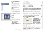
Cancellation of a finger print
To cancel a finger print, select it and, with the
right mouse button, click on "Cancel".
Reading and transfer (restore) of the finger
prints
If the system is composed of several finger print
readers and if they have all the same program-
user-finger print relation, it is not necessary to
repeat the reading procedure for each reader but
the finger prints can be copied from the first
device (master) onto the others.
The restore procedure permits reading of the
finger prints of the master device and saving of
them on the other finger print readers of the
system.
A -
Clicking on the icon of the reader on which
you wish to save the configuration of the
master device, the configuration window of
this reader is opened
Continue with the items G-O of the procedure
described on page 18.
B -
Select the address of the master reader
using the arrow up and down keys
C -
To load and view the configuration of the
selected reader/address click on the arrow
left key
D -
To save the configuration viewed on the
device to be configured (selected at item A)
click on the arrow right key.
E -
Remove the USB cable and quit the
maintenance mode. Then close the casing.


