background image

Balance Point

The Center of Gravity (C/G or Balance Point) is 72mm  from 
the leading edge of the TOP wing, measured at the center of 
the wing.
WARNING For test flying and general sport flying, we 
suggest you balance the airplane at the C/G recommended 
above. For 3D flying, you may want to experiment moving 
the C/G back in small increments until you're satisfied with 
the result.

Control


throws

Sport Flying
Ailerons: 

(

28mm

)

1

.

10

Up


and


Down

Elevator: 

(

32

.

4mm

)

1

.

28

"

Up


and


Down

Rudder: 

(

40mm

)

1

.

57

"

 Right


and


Left

3D Flying
Ailerons: 

(

70mm

)

2

.

76

"

 Up


and


Down

Elevator: 

(

81mm

)

3

.

19

"

 Up


and


Down

R udder: 

(

100mm

)

3

.

94

"

 Right


and


Left

The


control


throws


are


measured


from


the


widest


point


of


the


control


surfaces

Exponential

Sport Flying
Ailerons: 20%
Elevator: 20%
Rudder: 20%
3D Flying
Ailerons: 35% - 50%
Elevator: 35% - 50%
R udder: 35% - 50%
Exponential softens the response of the control surfaces 
around neutral stick. This makes the airplane easier to 
control while using such large control throws. The 
Exponential values shown are given as a percent. Please 
note that different brands of radio control systems may call 
for + or - Expo. Please check your transmitter's owners 
manual for more info.

Motor Thrust

To ensure great flight performance and 
to be able to trim your airplane properly, 
it is critical that you adjust the motor 
thrust as described. We suggest that 
you add 2 degrees of down-thrust and 1 
degrees of right-thrust. This can be 
achieved by adding a washer or two 
behind the top and right side of the 
motor (between the motor and the 
firewall). When set properly, the trim for 
the elevator and the rudder should be 
neutral. Fine-tune the down-thrust and 
right-thrust until this trim is achieved.

Summary of Contents for pulama 3D-EPP

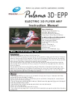
Page 1: ...rough them before beginning assembly EPP EPP EPP ELECTRIC 3D FLYER ARF Instruction Manual Specifications 865mm 34 1 in 800mm 31 5 in 400 sq in 25 8 sq dm Fuselage length Wingspan Wing Area Flying Weig...

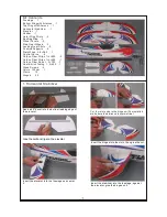
Page 2: ...1 4 400 1 Carbon Fiber Rods 1 3 700 7 Heat Shrink Tubing 1 5 400 1 Wood Screws 4 Velcro 100mm 1 Clevis 12 Hinges 25 Spoiling Flap Kit Contents Sand a 45 bevel into the bottom leading edge of the eleva...

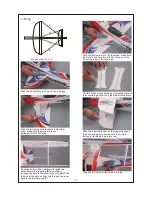
Page 3: ...glue the cut Insert the hinges into the then glue the cut slots Cut four slots where the hinges will be installed make sure the distance is symmetrical Cut slots the slots the same on wings and wing a...

Page 4: ...e sure A B C D Cut two carbon fiber strips as long as the slots of the outer wing struts then glue them to the slots Glue the top wing to the center wing mount and the outer wing struts make sure the...

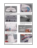
Page 5: ...tisfied with the alignment glue the landing gear strut to the fuselage side and the bottom wing Install the two wheels and wheel chocks Keep 1mm distance between wheel and its chock Apply some foam fr...

Page 6: ...tall the aileron elevator and rudder servos into the servo mounting hole in the fuselage Use some glue to secure them into place Because the size of servos differs you may need to cut the servo mounti...

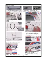
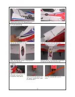
Page 7: ...ook and loop material Install the cabin door with the same way Glue the spoiling flap to the wing Install the elevator control linkage 380mm 7 Motor Apply some foam friendly C A into the four motor mo...

Page 8: ...20 Rudder 20 3D Flying Ailerons 35 50 Elevator 35 50 R udder 35 50 Exponential softens the response of the control surfaces around neutral stick This makes the airplane easier to control while using...

Reviews: