Technosoft 2016
37
iPOS4808 MY-CAN-STO/-CAT-STO Technical Reference
3.6.12 Removal from Autorun Mode
When the iPOS4808 is set in TMLCAN operation mode, it enters by default after power on in
Autorun
mode, if the drive
has in its local EEPROM a valid TML application (motion program), this is automatically executed as soon as the motor
supply V
MOT
is turned on.
In order to remove the drive from
Autorun
, you have 2 ways:
a) Software - by writing value 0x0001 in first EEPROM location, from address 0x4000;
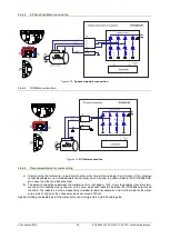
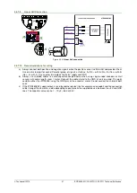
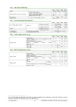
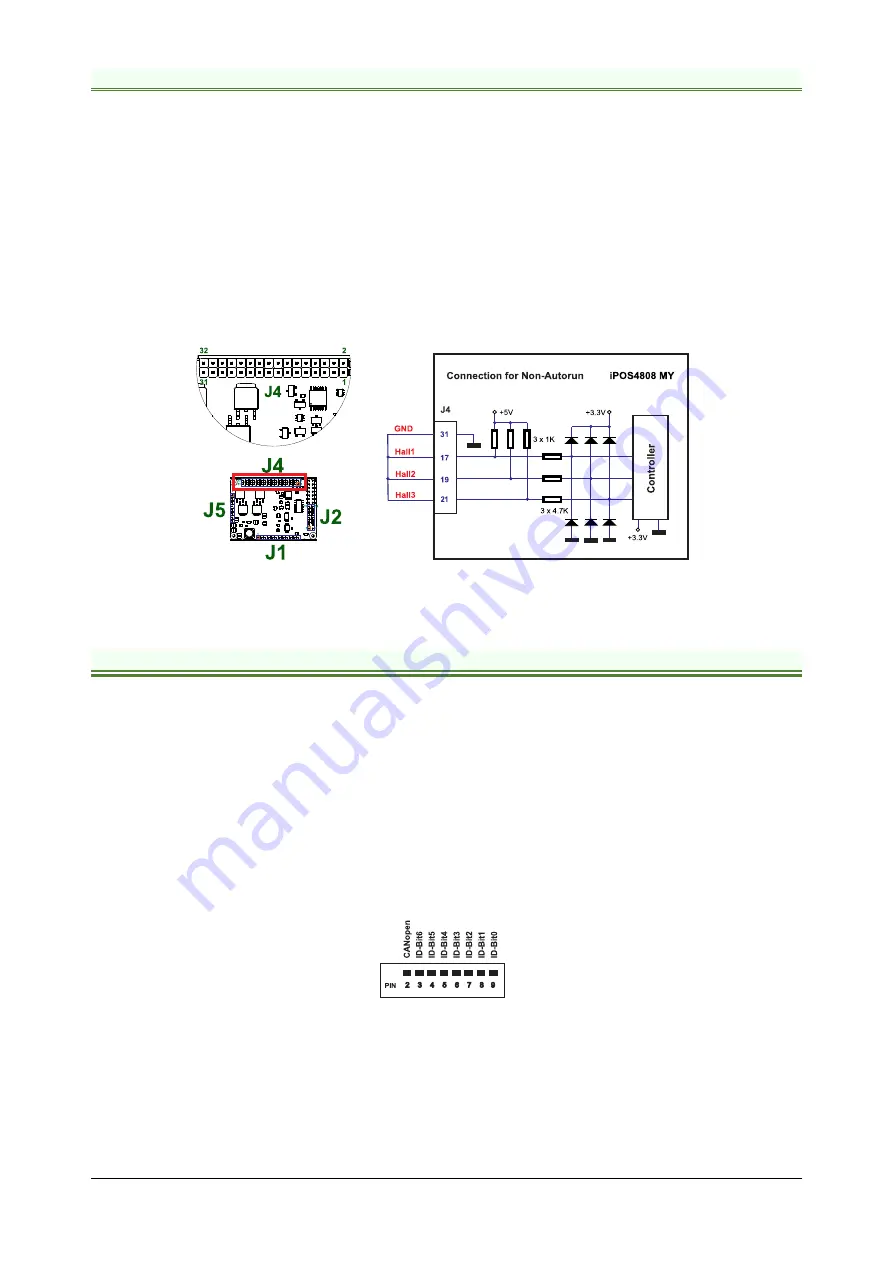
b) Hardware – by temporary connecting all digital Hall inputs to GND, during the power on for about 1s (until the
green led is turned on), as shown in
Figure 3.33
. This option is particularly useful when it is not possible to
communicate with the drive.
After the drive is set in
non-Autorun/slave
mode using 2
nd
method, the 1
st
method may be used to invalidate the TML
application from the EEPROM. On next power on, in absence of a valid TML application, the drive enters in the
non-
Autorun/slave
mode independently of the digital Hall inputs status.
Figure 3.33.
Temporary
c
onnection during power-on to remove the drive from
Autorun
mode
3.7 CAN Operation Mode and Axis ID Selection for CAN drives(J1 pin settings)
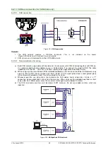
The communication protocol as well as the Hardware Axis ID can be set by connecting J1 pins to GND.
ON = connect pin to GND (pin 1)
OFF = leave pin unconnected
An 8 pole DIN switch can be connected to these pins on a user motherboard.
The CAN Operation mode is selected by pin2 of J1:
ON= CANopen mode / OFF= TMLCAN mode
The drive AxisID value is set after power on by:
-
Software, setting via EasySetUp a specific AxisID value in the range 1-255.
-
Hardware, by setting h/w in Easy setup under Axis ID value and selecting a value between 1-127 from the pins
3-9
Figure 3.34.
J1 – Axis ID pins
Pin 2
: On = CANopen mode; Off = TMLCAN mode
•
Pins 3 … 9
: ID-Bitx.
The drive axis/address number is set when H/W is selected in Drive Setup under AxisID field or when the
Setup is invalid.
The axis ID is an 8 bit unsigned number. Its first 7 bits are controlled by the ID-bit0 to ID-bit6. Bit7 of this
variable is always 0. In total, 127 axis ID HW values can result from the DIP switch combinations.
When pins 3..9 remain unconnected, the drive Axis ID will be 255.

