Technosoft iPOS4803-SY Technical Reference Download Page 8


 Technosoft 2022 

 8 

iPOS4803-SY Multi Axis System, EtherCAT Technical Reference


2  Product Overview 

2.1  Introduction 

The 

iPOS4803-SY 

is a family of fully digital intelligent servo drives, based on the latest DSP technology and they offer 

unprecedented drive performance combined with an embedded motion controller.  

Suitable for control of brushless DC, brushless AC (vector control)  and DC brushed motors the iPOS4803-SY Multi 

Axis System accept as position feedback incremental encoders, absolute encoders (SSI,  BiSS-C, EnDAT, 

TAMAGAWA, Panasonic, Nikon, Sanyo Denki), digital and linear Hall signals. 

All drives perform position, speed or torque control and work in single, multi-axis or stand-alone configurations. 

Thanks to the embedded motion controller, the iPOS4803-SY Multi Axis System combine controller, drive and PLC 

functionality in a single compact unit and are capable to execute complex motions without requiring intervention of an 

external motion controller. Using the high-level Technosoft Motion Language (

TML

) the following operations can be 

executed directly at drive level: 

  Setting various motion modes (profiles, PVT, PT, electronic gearing

1

 or camming

1

, etc.) 

  Changing the motion modes and/or the motion parameters 

  Executing homing sequences 

  Controlling the program flow through: 

  Conditional jumps and calls of TML functions 

  TML interrupts generated on pre-defined or programmable conditions  (protections  triggered, 

transitions on limit switch or capture inputs, etc.)  

  Waits for programmed events to occur  

  Handling of digital I/O and analogue input signals  

  Executing arithmetic and logic operations 

  Performing data transfers between axes 

  Synchronizing all the axes from a network  

By implementing motion sequences directly at drive level you can really distribute the intelligence between the master 

and the drives in complex multi-axis applications, reducing both the development time and the overall communication 

requirements. For example, instead of trying to command each movement of an axis, you can program the drives 

using TML to execute complex motion tasks and inform the master when these tasks are done. Thus, for each axis 

control the master job may be reduced at: calling TML functions  stored in the drive EEPROM and waiting for a 

message, which confirms the TML functions execution completion.  

For iPOS4803-SY commissioning 

EasySetUp

 or 

EasyMotion Studio

 PC applications may be used. 

EasySetUp

 is a subset of EasyMotion Studio, including only the drive setup part. The output of EasySetUp is a set of 

setup data that can be downloaded into the drive EEPROM or saved on a PC file. At power-on, the drive is initialized 

with the setup data read from its EEPROM. With EasySetUp it is also possible to retrieve the complete setup 

information from a drive previously programmed. EasySetUp shall be used for drive setup in all cases where the 

motion commands are sent exclusively from a master. Hence neither the iPOS4803-SY TML programming capability 

nor the drive camming mode are used. 

EasySetUp can be downloaded free of charge from Technosoft web 

page.


EasyMotion Studio

  platform includes EasySetUp  for the drive setup, and a 

Motion Wizard

  for the motion 

programming. The Motion Wizard provides a simple, graphical way of creating motion programs and automatically 

generates all the TML instructions. 

With EasyMotion Studio you can execute complex motions, thanks to their built-in 

motion controller

s. EasyMotion Studio, may be used to program motion sequences in TML. 

A demo version of EasyMotion Studio (with EasySetUp part fully functional) can be downloaded free of 

charge from Technosoft web page.


1

 Available if the master axis sends its position via a communication channel, or by using the secondary encoder input 

Summary of Contents for iPOS4803-SY

Page 1: ...iPOS4803 SY Multi Axis System EtherCAT Intelligent Servo Drive for DC Brushless DC and AC Motors Intelligent Servo Drives Technical Reference Technosoft 2022 P091 020 iPOS4803 SY UM 0822 ...

Page 2: ... 3 Hardware Installation 12 3 1 iPOS4803 SY Multi Axis System Dimensions 12 3 2 Mechanical Mounting 12 3 3 Connectors and Pinouts 13 3 3 1 Pinouts for iPOS4803 SY3 Multi Axis System 13 3 3 2 Pinouts for iPOS4803 SY4 Multi Axis System 14 3 3 3 Mating Connectors for iPOS4803 SY Multi Axis System 15 3 4 Connection diagrams 16 3 5 Digital I O Connection 17 3 5 1 NPN inputs 17 3 5 2 NPN outputs 17 3 6 ...

Page 3: ...Hall Incremental Encoder 24 3 8 10 Digital Hall Connection for direct motor control without an encoder 24 3 8 10 1 General recommendations for feedback wiring 25 3 9 Power Supply Connection 25 3 9 1 Supply Connection 25 3 9 1 1 Recommendations for Supply Wiring 25 3 9 1 2 Recommendations to limit over voltage during braking 26 3 10 USB connection 27 3 10 1 USB connection 27 3 11 EtherCAT Connectio...

Page 4: ...20 200 P404 4 Axis Motion System 3A nominal EtherCAT In order to operate the iPOS4803 SY drives you need to pass through 3 steps Step 1 Hardware installation Step 2 Drive setup using Technosoft EasySetUp software for drive commissioning Step 3 Motion programming using one of the options An EtherCAT master The drives built in motion controller executing a Technosoft Motion Language TML program deve...

Page 5: ...raphical way of creating motion programs and automatically generates all the TML instructions With EasyMotion Studio you can fully benefit from a key advantage of Technosoft drives their capability to execute complex motions without requiring an external motion controller thanks to their built in motion controller A demo version of EasyMotion Studio with EasySetUp part fully functional can be down...

Page 6: ...structions listed hereunder This information is intended to protect you the drive and the accompanying equipment during the product operation Incorrect handling of the drive can lead to personal injury or material damage The following safety symbols are used in this manual WARNING SIGNALS A DANGER TO THE OPERATOR WHICH MIGHT CAUSE BODILY INJURY MAY INCLUDE INSTRUCTIONS TO PREVENT THIS SITUATION CA...

Page 7: ...dard ISO 9001 2015 Quality Austria Certificate about the application and further development of an effective Quality Management System complying with the requirements of Standard ISO 9001 2015 REACH Compliance TECHNOSOFT hereby confirms that this product comply with the legal obligations regarding Article 33 of the European REACH Regulation 1907 2006 Registration Evaluation Authorization and Restr...

Page 8: ...te the intelligence between the master and the drives in complex multi axis applications reducing both the development time and the overall communication requirements For example instead of trying to command each movement of an axis you can program the drives using TML to execute complex motion tasks and inform the master when these tasks are done Thus for each axis control the master job may be r...

Page 9: ...anasonic Nikon Sanyo Denki encoder interface 2nd feedback devices supported Incremental encoder interface differential Pulse direction interface differential for external master digital reference BISS SSI EnDAT TAMAGAWA Panasonic Nikon Sanyo Denki encoder interface Separate feedback devices supported Hall sensors interface digital or linear 1 analogue input 16bit 10V or 12 bit 0 5V Reference Feedb...

Page 10: ...803 can have the following part numbers and names on the identification label P020 200 E403 iPOS4803 SY3 3 Axis Motion System 3A nominal EtherCAT hardware AxisID P020 200 E404 iPOS4803 SY4 4 Axis Motion System 3A nominal EtherCAT hardware AxisID P020 200 P404 iPOS4803 SY4 4 Axis Motion System 3A nominal EtherCAT 1 Where x can be 1 2 or 3 for iPOS4803 SY3 or 1 2 3 or 4 for iPOS4803 SY4 ...

Page 11: ... diff Yes Yes Yes Tacho Analogue input Feedback Yes 2 4 2 Dual loop configurations The motor speed control loop is closed on one feedback connected on the motor while the motor position control loop is closed on the other available feedback which is placed on the load There is usually a transmission between the load and the motor Motor type Feedback 1 Feedback 2 PMSM Incremental encoder single end...

Page 12: ...in mm The drawings are not to scale 3 2 Mechanical Mounting The iPOS4803 SY Multi Axis System is intended to be mounted vertically or horizontally on a metallic support using the provided mounting holes and the recommended mating connectors The recommended inserts and screws are Image Connector Description Manufacturer Part Number Self clinching nuts M3 PennEngineering PEM KF2 M3 ET Screws M3x10 B...

Page 13: ... Technosoft 2022 13 iPOS4803 SY Multi Axis System EtherCAT Technical Reference 3 3 Connectors and Pinouts 3 3 1 Pinouts for iPOS4803 SY3 Multi Axis System Where x can be 1 2 or 3 ...

Page 14: ... Technosoft 2022 14 iPOS4803 SY Multi Axis System EtherCAT Technical Reference 3 3 2 Pinouts for iPOS4803 SY4 Multi Axis System Where x can be 1 2 3 or 4 ...

Page 15: ...333 J8 x Pico Clasp Receptacle Crimp Housing 1 00mm Pitch Single Row Friction Lock 5 Circuits White Molex 5013300500 J1 J9 J2 x Pre Crimped wires for Nano Fit Cable Assembly Nano Fit Crimp Terminal Socket to Nano Fit Crimp Terminal Socket 300mm Molex 0797582140 J3 x J4 x J8 x Pre Crimped wires for Pico Clasp Cable Assembly Pico Clasp Crimp Terminal Socket to Pico Clasp Crimp Terminal Socket 300mm ...

Page 16: ...nection diagrams Figure 3 iPOS4803 SY Multi Axis System Connection diagram Where x can be 1 2 or 3 for iPOS4803 SY3 or 1 2 3 or 4 for iPOS4803 SY4 For other available feedback motor options check the detailed diagrams below Pins are software selectable individually as NPN inputs outputs ...

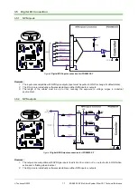
Page 17: ...he I O pins are individually software selectable as either NPN inputs or outputs 3 The length of the cables must be up to 30m reducing the exposure to voltage surges in industrial environment 3 5 2 NPN outputs Figure 5 Digital NPN Outputs connection for iPOS4803 SY Remarks 1 The outputs are compatible with NPN type inputs load is tied to common VLOG output pulls to GND when active and is floating ...

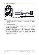
Page 18: ...to the drive ground shield will be connected to the drive ground terminal b If the analogue signal source is differential and the signal source ground is isolated from the drive GND use a 2 wire twisted shielded cable as follows 1st wire connects the source plus positive in phase to the drive analogue input 2nd wire connects the source minus negative out of phase to the drive ground GND Shield is ...

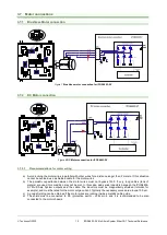
Page 19: ...e for the motor wires b The parasitic capacitance between the motor wires must not bypass 10nF If very long cables tens of meters are used this condition may not be met In this case add series inductors between the iPOS4803 SY Multi Axis System outputs and the cable The inductors must be magnetically shielded toroidal for example and must be rated for the motor surge current Typically the necessar...

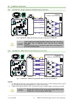
Page 20: ...nnected to system GND to avoid disturbances noise induced by nearby cables 3 8 2 Feedback 1 Differential Incremental Encoder Connection Figure 10 Feedback 1 Differential Incremental Encoder Connection for iPOS4803 SY Remarks 1 For iPOS4803 SY Multi Axis System Feedback 1 differential connection 120Ω 0 25W termination resistors are internally added by putting the SW1 x pins 1 2 and 3 on ON position...

Page 21: ...rial environment CAUTION Encoder cable shield must be connected to system GND to avoid disturbances noise induced by nearby cables 3 8 4 Feedback 1 Absolute Encoder Connection SSI BiSS EnDAT Figure 12 Feedback 1 Absolute Encoder Connection for iPOS4803 SY Remarks 1 For iPOS4803 SY Multi Axis system Feedback 1 absolute connection 120Ω 0 25W termination resistors are internally added by putting the ...

Page 22: ...xposure to voltage surges in industrial environment CAUTION Encoder cable shield must be connected to system GND to avoid disturbances noise induced by nearby cables 3 8 6 Feedback 2 Absolute Encoder Connection SSI BiSS EnDAT Figure 14 Feedback 2 Absolute Encoder Connection for iPOS4803 SY Remarks 1 For iPOS4803 SY Multi Axis System Feedback 2 input has internal termination resistors equivalent to...

Page 23: ...al termination resistors equivalent to 120Ω 0 25W present in the drive 2 The length of the cables must be up to 30m reducing the exposure to voltage surges in industrial environment CAUTION Encoder cable shield must be connected to system GND to avoid disturbances noise induced by nearby cables 3 8 8 Linear Analog Hall Connection Figure 16 Linear Hall connection for iPOS4803 SY CAUTION Analog Hall...

Page 24: ...ects breakage of Hall wires and or of incremental absolute encoder wires 1 3 The length of the cables must be up to 30m reducing the exposure to voltage surges in industrial environment CAUTION Digital Hall cable shield must be connected to system GND to avoid disturbances noise induced by nearby cables 3 8 10 Digital Hall Connection for direct motor control without an encoder Figure 18 Digital Ha...

Page 25: ...sing single ended encoders or Hall sensors with cable lengths over 1 meter Connect the cable shield to the GND at both ends a If the 5V supply output is used by another device like for example an encoder and the connection cable is longer than 5 meters add a decoupling capacitor near the supplied device between the 5V and GND lines The capacitor value can be 1 10 μF rated at 6 3V 3 9 Power Supply ...

Page 26: ...al or bigger than the maximum expected over voltage and can be sized with the formula 2 2 2 NOM MAX M U U E C where UMAX 52V is the over voltage protection limit UNOM is the nominal motor supply voltage EM the overall energy flowing back to the supply in Joules In case of a rotary motor and load EM can be computed with the formula F M d d Ph 2 M final initial L M 2 M L M M T 2 t t R 3I h g h m m J...

Page 27: ...n Windows 10 and the device is identified as a COM port In Easy Motion studio choose the following communication settings Figure 21 USB connection Instead of COM1 choose the new COM value detected after the driver is installed Remark 1 EasyMotion Studio can communicate either with RS232 or USB communication not both at the same time 2 EasyMotion Studio can communicate in parallel with RS232 USB co...

Page 28: ... 2nd port of the master This topology consists of the linear topology described above plus an extra connection between the master which has two RJ45 ports to OUT of the last drive See Figure 23 for a visual representation of the ring topology Ring topology is preferred for its added security since it is insensitive to one broken cable connection along the ring re routing of communication is done a...

Page 29: ...to the drive disconnect the hall sensors from GND and execute a new power off power on cycle Figure 24 Temporary connection during power on to invalidate the Setup table for iPOS4803 SY 3 13 Axis ID Selection for CAT drives1 The iPOS4803 SY Multi Axis System support all EtherCAT standard addressing modes In case of device addressing mode based on node address the iPOS4803 SY Multi Axis System driv...

Page 30: ...e 3 Drive 4 off off off off off 1 2 3 4 off off off off on 9 10 11 12 off off off on off 17 18 19 20 off off off on on 25 26 27 28 off off on off off 33 34 35 36 off off on off on 41 42 43 44 off off on on off 49 50 51 52 off off on on on 57 58 59 60 off on off off off 65 66 67 68 off on off off on 73 74 75 76 off on off on off 81 82 83 84 off on off on on 89 90 91 92 off on on off off 97 98 99 10...

Page 31: ...nt drives 10 mm Between drives and nearby walls 10 mm Space needed for drive removal TBD mm Between drives and roof top 30 mm Insertion force Using recommended mating connectors TBD TBD N Extraction force TBD TBD N 3 14 4 Environmental Characteristics Min Typ Max Units Size Length x Width x Height Global size Without connectors Whole System 84 8 x 94 8 x 28 1 mm 3 33 x 3 73 x 1 1 inch Weight g Cle...

Page 32: ...measurement range VMOT 48 V FPWM 20 kHz TBD µH FPWM 40 kHz TBD FPWM 60 kHz TBD FPWM 80 kHz TBD FPWM 100 kHz TBD Absolute minimum value limited by short circuit protection VMOT 48 V FPWM 20 kHz TBD µH FPWM 40 kHz TBD FPWM 60 kHz TBD FPWM 80 kHz TBD FPWM 100 kHz TBD Motor electrical time constant L R Recommended value for 5 current measurement error due to ripple FPWM 20 kHz TBD µs FPWM 40 kHz TBD F...

Page 33: ...nternal 2 2KΩ pull up to 5 0 Minimum pulse width 70 µs ESD protection Human body model 15 kV 3 14 4 Encoder Inputs A1 A1 B1 B1 Z1 Z1 A2 A2 B2 B2 Z2 Z2 Min Typ Max Units Differential mode compliance For full RS422 compliance see 1 TIA EIA 422 A Input voltage Hysteresis 0 06 0 1 0 2 V Differential mode 14 14 Common mode range A to GND etc 11 14 Input impedance differential A A2 B B2 Z Z2 2 2 kΩ A A2...

Page 34: ... DT CK T T 2 1 2 3 4 5 m 3 m 2 m 1 m MSB LSB m multi turn bits n n 1 n 2 n 3 n 4 4 3 2 1 m 1 m 2 m 3 m 4 m 5 m n 3 m n 2 m n 1 m n MSB LSB n single turn bits CK and DT signals have the same form with CK and DT but with opposite polarity 3 14 7 Supply Output 5V Min Typ Max Units 5V output voltage Current sourced 400mA 4 9 5 5 2 V 5V output current 1 TBD mA Short circuit protection Yes Over voltage ...

Page 35: ...ating with motor supply Figure 31 iPOS4803 Microdrive Output Voltage De rating with PWM frequency 0 2 4 6 0 50 100 150 200 Current amplitude A PWM Frequency KHz Micro 24V 0 2 4 6 0 15 30 45 60 75 Current amplitude A Ambient Temperature ºC Micro 20KHz 24V 0 1 2 3 4 5 6 0 5 10 15 20 25 30 35 40 45 50 Current amplitude A Vmot V Micro 20KHz 0 50 100 0 50 100 150 200 Output Voltage V OUT V MOT PWM Freq...

Page 36: ...ring run time The E2 ROM is mapped in the address range 2000h to 7FFFh It is used to keep in a non volatile memory the TML programs the cam tables and the drive setup information Remark EasyMotion Studio handles automatically the memory allocation for each motion application The memory map can be accessed and modified from the Memory Settings dialogue of each application Figure 32 iPOS4803 SY Memo...

Reviews: