


©
Technosoft 2007
34
IBL2403 Technical Reference
3.2.10. Supply connection
3.2.10.1 Supply connection
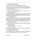
J2
Power supply connection
+3.3V
DC
DC
GND
+V
DC
+
12...28V
+5V
DC
DC
+5V
OUT
To motor
IBL2403
v1.1
Mo
ti
o
n
C
h
ip
TM
J2
J1
+5V
OUT
0.
2
A
max
OUTPUT
OUTPUT
Figure 3.20.
Supply connection
3.2.10.2 Recommendations for Supply Wiring
Use short, thick wires between the IBL2403 and the motor power supply. If the wires are longer
than 2 meters, use twisted wires for the supply and ground return. For wires longer than 20
meters, add a capacitor of at least 1000
μ
F (rated at an appropriate voltage) right on the terminals
of the IBL2403.
3.2.10.3 Recommendations to limit over-voltage during braking
During abrupt motion brakes or reversals the regenerative energy is injected into the motor power
supply. This may cause an increase of the motor supply voltage (depending on the power supply
characteristics). If the voltage bypasses the U
MAX
value, the drive over-voltage protection is
triggered and the drive power stage is disabled.
Summary of Contents for IBL2403 Series
Page 2: ......
Page 4: ......
Page 8: ... Technosoft 2007 VI IBL2403 Technical Reference ...
Page 89: ......
Page 90: ......


