background image


TOP 600 XTPRO: Service & Maintenance Manual - rev. 2.0


Page 11.4 

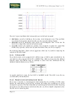
Sensitivity is reduced by soldering a resistor in parallel with the coil. Normally, the receiver already 
has a 15 KOhm resistor mounted in parallel with the coil, however it is advisable to check for its 
presence. 
 
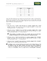
The following table shows the nominal values of reception distance based on the value of the 
resistor soldered on the coil: 
 

RESISTANCE

(Ohm) 

DISTANCE 

(cm) 

15K 89 
13K 88 
11K 87 
9K1 85 
6K8 84 
5K1 81 

3K 74 
2K 69 
1K 57 

 
Please note that these are only nominal values. The actual reduction in sensitivity must be verified 
experimentally, taking great care not to excessively reduce the reception distance. 
 

  WARNING: if there is already a 15 KOhm resistor mounted in parallel with the coil, 

note that adding another resistor in parallel will produce a total resistance value 
equivalent to the parallel combination of the added resistor and the existing 15 KOhm 
resistor.  

11.1.4.   M

ECHANICAL VIBRATIONS


Mechanical vibrations may cause slight shifting of the coil, giving rise to transient impulses. If 
these transients occur only occasionally they can be easily filtered by SW. However, if the 
mechanical vibrations are periodic, they can produce periodic pulses which may be interpreted as 
correct heart rate values. 
 
To eliminate or reduce the effects of vibration, house the receiver between the foam pads in such a 
way that any vibrations are correctly damped. 

11.1.5.   P

OSITION OF THE RECEIVER


Carefully position the receiver according to the specifications below: 
 

• 

the coil must be directed toward the user; 

• 

the coil must be positioned well away (even a few centimeters) from the LEDs; 

• 

the cable must be folded immediately after the connection on the receiver, so that it does not 
pass near the coil; 

• 

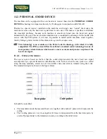
the receiver must be directed in such a way that its axis of reception is parallel to that of the 
transmitter, as shown in the figure below: 

Summary of Contents for Top 600 XTPRO

Page 1: ...SERVICE MAINTENANCE MANUAL REV 2 0...

Page 2: ......

Page 3: ...THE MACHINE IS TURNED OFF NOTE The information contained in this document is subject to change without notice Technogym does not guarantee this documentation in any way Technogym shall not be held res...

Page 4: ......

Page 5: ...lternator 3 3 3 1 7 Power resistor 3 3 3 2 ALTERNATOR CONTROL 3 4 3 2 1 Mechanics 3 4 3 2 2 Control 3 4 3 2 3 The control signals 3 5 4 ACCESSORIES 4 1 4 1 CONNECTING TO THE TGS 4 1 4 2 CONNECTING TO...

Page 6: ...AL SETTING PARAMETERS 9 3 9 2 1 Enabling use of the hand sensor 9 3 9 2 2 Enabling the display mode 9 4 9 3 MAINTENANCE INFORMATION 9 4 9 3 1 Hours on 9 4 9 3 2 Hours of use 9 4 9 4 CHANGING THE MAINT...

Page 7: ...Mechanical vibrations 11 4 11 1 5 Position of the receiver 11 4 11 2 PERSONAL CODED DEVICE 11 6 11 2 1 Operating modes 11 6 12 TOP 600 XTPRO IFI 12 1 12 1 DISASSEMBLY OF COMPONENTS 12 2 12 1 1 Disasse...

Page 8: ...TOP 600 XTPRO Service Maintenance Manual rev 2 0 Page iv Page intentionally left blank...

Page 9: ...vance may cause damage to the machine Information about the operation in progress OBSERVE observation about the operation in progress 1 2 RECOMMENDATIONS Technogym recommends the following steps for p...

Page 10: ...recommended brands 3 Use special tools where specified 4 Consult the Technical Newsletters which may contain more up to date information on adjustments and maintenance than those contained in this ma...

Page 11: ...z Consumption 160 Watt 1 71 0 86 A Fuses 5x20 3 A fast blow 2 3 AMBIENT SPECIFICATIONS Operating from 5 to 35 C Temperature Storage from 20 to 55 C Operating from 30 to 80 non condensing Humidity Stor...

Page 12: ...TOP 600 XTPRO Service Maintenance Manual rev 2 0 Page 2 2 2 5 WIRING DIAGRAM WITH NON CODED RECEIVER...

Page 13: ...10 pin to CPU board Power supply Name type of connector connection CN1 PANDUIT 6 pin to mains power supply CN2 PANDUIT 7 pin to alternator interface board FG Faston to ground Alternator interface boa...

Page 14: ...ton Neutral Black 6 TX 5 L Alternator cable Alternator interface board Alternator Resistor Alternator interface board CN2 Signal Color Alternator Resistor 1 Alternator RPM X 6 Violet Red eyelet 4 2 Re...

Page 15: ...Tx to TGS flat 3 4 5 Vdc flat 4 5 Rx from TGS flat 5 6 Tx to PC flat 6 7 Ground flat 7 8 Rx from PC flat 8 9 Ground flat 9 10 Ground flat 10 CR XT Non coded heart rate meter cable CPU board Cardio rec...

Page 16: ...tenance Manual rev 2 0 Page 2 6 2 6 WIRING DIAGRAM WITH CODED RECEIVER The only difference compared to the model with non coded receiver is the NSC XT cable between the CPU board and the coded receive...

Page 17: ...XTPRO Service Maintenance Manual rev 2 0 NSC XT Non coded heart rate meter cable CPU board Cardio receiver CPU board CN4 Signal Color Receiver 1 5 Vdc Red 2 2 Pulse per beat Blue 1 6 Ground Black 3 P...

Page 18: ...TOP 600 XTPRO Service Maintenance Manual rev 2 0 Page 2 8 Page intentionally left blank...

Page 19: ...e block diagram of the machine is shown in the figure below 3 1 1 DISPLAY It consists of various components that will be individually described below CARDIO RECEIVER It is connected to the machine s C...

Page 20: ...selected with the keys or according to the chosen training program 3 1 2 CARDIO TRANSMITTER It is worn by the person using the machine and transmits to the cardio receiver one pulse for every heart be...

Page 21: ...PM signal 6 impulses per revolution necessary for counting the number of revolutions and hence measuring the speed Its rotation produces energy which is dissipated by the power resistor There is a the...

Page 22: ...this the CPU board transmits a PFM Pulse Frequency Modulation signal The alternator interface board converts the PFM signal into an analogue signal which serves as the excitation signal for the altern...

Page 23: ...h variable frequency The logic of this control causes the frequency to increase with increasing resistance This signal enters the alternator interface board pin 6 3 of connector CN1 and is converted i...

Page 24: ...2 and is a square wave which varies from 1 Vdc to a maximum value dependent on the training speed as illustrated in the figure below The signal is cleaned and level converted before being sent from th...

Page 25: ...ol panel Retrofit Control panel DB9 male Signal Color Retrofit 1 12 Vdc Yellow 8 5 Ground Green 6 3 Rx Brown 2 2 Tx White 1 For all further information including troubleshooting refer to the following...

Page 26: ...TOP 600 XTPRO Service Maintenance Manual rev 2 0 Page 4 2 Page intentionally left blank...

Page 27: ...0 Watt 9 The machine can be connected in cascade with other machines It is recommended to connect only machines of the same type in cascade up to a maximum of 5 machines In this case make sure that th...

Page 28: ...power on test which sounds the buzzer lights all the LEDs At the end of the power on test the machine enters standby mode awaiting a keyboard command To check the correct operation of the machine sta...

Page 29: ...type of box is a step in the troubleshooting procedure where an ACTION must be carried out It typically contains a description of the ACTION necessary to resolve the problem Therefore after executing...

Page 30: ...tput supply the correct voltage Is the mains lead OK VAre the fuses OK Connect machine to a suitable electrical output Replace the mains lead Replace the blown fuses Replace the input socket on off sw...

Page 31: ...er Replace cable connecting the filter to the power supply Replace the power supply YES NO YES NO YES 3 4 5 Is the mains voltage present at the filter input 2 Replace cable connecting the input socket...

Page 32: ...measured voltage should be approximately 220 VAC or 110 VAC depending on the mains electricity supply 2 As for step 1 but with the tester probes at the filter input 3 As for step 1 but with the teste...

Page 33: ...r excitation circuit ok Execute the procedure The resistance is incorrect YES Is the alternator overheated NO Allow it to cool down and then try again The thermal cutout is probably tripped YES Replac...

Page 34: ...ernator interface board correct Is the power resistor value correct Replace the power resistor Check and or replace cable between alternator and alternator interface board YES NO YES NO NO YES 1 2 3 D...

Page 35: ...ser weight 2 As for step 2 but with the tester between pins 4 and 5 of connector CN2 on the alternator interface board 3 Disconnect all the cables from the 2 power resistor terminals Place the tester...

Page 36: ...s the SPM signal on connector CN2 of the alternator interface board correct Is the SPM signal on connector CN1 of the alternator interface board correct Rewire the cable correctly Replace the alternat...

Page 37: ...an oscilloscope between the violet wire and the alternator ground When the speed is varied the waveform frequency should vary as shown in the table below RPM FREQUENCY Hz 60 180 70 210 80 240 3 As fo...

Page 38: ...Replace or repair cable between CPU board and receiver Replace the display CPU board 1 2 YES NO YES NO Follow the procedure step by step to correctly diagnose the problem Take particular care with th...

Page 39: ...n machines OK Is the receiver positioned correctly and are the connecting cables correctly routed Are there sources of electromagnetic noise near the receiver Move the machines to the minimum distance...

Page 40: ...detail below 1 To check for electromagnetic noise near the machine use a frequency signal monitor constructed as shown in the schematic below The circuit lights the LED for every heart beat and or di...

Page 41: ...mains lead from the wall output 2 Remove the 4 screws a using a large Phillips screwdriver Support the DISPLAY before removing the last screw Figure 7 1 2 3 Open the DISPLAY taking care to the RJ45 RS...

Page 42: ...sing an integrated circuit extractor tool Figure 7 2 2 To reassemble the EPROM 1 Make sure that reference notch b on the EPROM coincides with reference notch c on its socket 2 Be careful to center the...

Page 43: ...the display With the display on a work bench 1 Disconnect the connectors a 2 Unscrew the 5 screws b using a small Phillips screwdriver 3 Disconnect the cardio receiver connector if it is still connec...

Page 44: ...eassemble the new KEYBOARD with the display on a work bench 1 Remove the backing film from the adhesive 2 Apply the adhesive part starting from the left and working towards the right without folding t...

Page 45: ...d unplug the mains lead from the wall outlet On both sides of the machine 2 Unscrew knob a 3 Unscrew the self locking nut which is underneath the knob a with a 17 mm wrench 4 Remove the compensating r...

Page 46: ...e the 5 self tapping screws c which fix the LEFT GUARD to the frame using a large Phillips screwdriver 4 Remove screw d using a large Phillips screwdriver while using another large Phillips screwdrive...

Page 47: ...Back off the 2 fixing bolt a with a 3 mm hex T wrench while using a 7 mm wrench to hold its nut in place 2 Remove the housing Figure 7 7 2 3 Open the housing 4 Disconnect connector b 5 Remove the REC...

Page 48: ...2 Unscrew the fixing screws on the support plate using a 7 mm socket wrench 3 Manually unscrew the fixing studs of the protective grill 4 Remove the circuit board To disassemble the ALTERNATOR INTERF...

Page 49: ...using a 19 mm wrench 4 Back off dowel c using a 4 mm hex T wrench 5 Move the ALTERNATOR until belt d can be removed To facilitate the operation the belt can first be removed from the pulley 6 Loosen l...

Page 50: ...ternator until BELT c can be removed To facilitate the operation the belt can first be removed from the pulley Figure 7 10 2 From both sides of the machine 4 Use a marker pen to fix a reference index...

Page 51: ...sing the special pliers 8 Push the pin toward the right until there is enough space for BELT to pass through 9 Remove the BELT To reassemble the BELT follow the above steps in reverse order After comp...

Page 52: ...gs 1 Turn the CHAIN until the connecting link a is on the sprocket wheel b 2 Release clip c from the link using the special pliers 3 Remove the connecting plate d 4 Remove the connecting link a 5 Remo...

Page 53: ...e belt and 7 11 Disassembling the chain Working from the left side 1 Push pin a until it comes out from the right side 2 Remove the PULLEY from the side After completing the procedure adjust the align...

Page 54: ...e right and left side casings 1 Disengage the chain from the PRIMARY SHAFT sprocket by opening the dummy link 2 Unscrew the 4 screws a with a 17 mm wrench 3 Disassemble the PRIMARY SHAFT To reassemble...

Page 55: ...hine SADDLE up to remove 3 Back off the screw which clamps knob a using a 4 mm hex T wrench 4 Remove knob a and the pin supporting it with one hand to prevent it from falling inward 5 On both sides of...

Page 56: ...ht and left HANDLES 1 Grasp the HANDLE as shown in the figure at left 2 Using a 5 mm hex wrench unscrew the handle 3 Remove the HANDLE The LEFT HANDLE has an inverse thread and must therefore be unscr...

Page 57: ...ut the procedures described in paragraph 7 6 Disassembling the right and left side casings 1 Disconnect cable a from the alternator 2 Back off the BRUSH group clamping screw b using a medium Phillips...

Page 58: ...TOP 600 XTPRO Service Maintenance Manual rev 2 0 Page 7 18 Page intentionally left blank...

Page 59: ...nator pivot b using a 4 mm hex T wrench 3 Placing a straight reference rod d against pulley e verify the alignment of belt f by checking that the reference rod d is parallel with belt f 4 Adjust alter...

Page 60: ...b using a 19 mm wrench 2 Back off dowel c of alternator pin b using a 4 mm hex T wrench 3 Back off nut d of the belt tension rod e using a 17 mm wrench 4 Rotate the alternator on pin b in such a way...

Page 61: ...fixing the primary shaft with a 5 mm hex T wrench 2 Move the primary shaft by the amount necessary to obtain alignment of the chain 3 After completing the adjustment lock down what previously backed o...

Page 62: ...rame using a 4 mm hex T wrench 2 Turn the cams in a clockwise or anticlockwise direction to loosen or tighten the chain until the vertical play at point A is approximately 1 cm 3 Check the amount of p...

Page 63: ...re 8 5 1 Carry out the procedure described in paragraph 7 14 Disassembling the saddle and stem guard For all the screws 1 Loosen the stop nut a using a 17 mm wrench 2 Adjust the amount of play by mean...

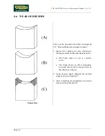
Page 64: ...s 1 Inspect the 2 brushes for wear referring to the figures at left and the descriptions below The brush shown in A is correctly worn The brush shown in B is irregularly worn and may result in noise a...

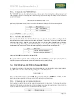
Page 65: ...automatically shown in the chosen language To change the current setting when the language actually in use will scroll on the LED matrix press the proper numeric key from 1 to 6 to choose the desired...

Page 66: ...essions in CPR mode To change the current setting when the setting is actually in use will scroll on the LED matrix KEYS CPR xxx press the proper numeric key 1 or 2 to choose the desired setting as fo...

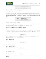
Page 67: ...ent priority value press the number keys from 1 to 2 to set the desired priority as shown in the following table KEY PRIORITY 1 CHEST BAND PRIORITY 2 HEART SENSOR PRIORITY then press ENTER to confirm...

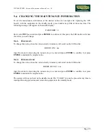
Page 68: ...me to interrupt the setup procedure and return the equipment to the standby mode 9 3 MAINTENANCE INFORMATION In order to perform regular maintenance correctly the actual number of hours the equipment...

Page 69: ...S ON To change this value when the value actually in memory will scroll on the LED matrix HOURS ON xxx input the desired value using the numeric keys to enter and press ENTER to confirm Just press ENT...

Page 70: ...TOP 600 XTPRO Service Maintenance Manual rev 2 0 Page 9 6 Page intentionally left blank...

Page 71: ...EANING OPERATIONS These operations can be carried out by the owner of the machine and do not require any special skills The external cleaning operations are involve simple cleaning for the purposes of...

Page 72: ...ns at least once a month For internal cleaning of the machine proceed as follows 10 2 1 SETTING UP THE OPERATION 1 Turn off the machine by placing the switch in the 0 position OFF 2 Unplug the mains l...

Page 73: ...machine guards 10 3 2 CHECKING THE WORKING CONDITIONS 1 Check that the machine is connected directly to the wall outlet without any extension cords and that the outlet is correctly earthed 2 If the ma...

Page 74: ...e shifts in body weight Adjust the amount of play if necessary 10 3 10 CHECKING THE OPERATION OF THE CARDIO RECEIVER 1 Using a separate heart rate monitor put on the transmitter strap and check that t...

Page 75: ...n in the figure below which consists of Figure 11 1 1 an antenna a designated the coil which receives the signal from the transmitter strap worn by the user an integrated circuit b designated the ASIC...

Page 76: ...nal 11 1 1 TYPE OF ASIC The cardio receivers can be equipped with 3 different types of ASIC models identifiable by the code marked on the component MAS FTC or HRRE These ASICs are characterized by dif...

Page 77: ...d identify its source The only effective solution in the presence of electromagnetic interference is to reduce the power of the noise source using a trial and error method based principally on Shieldi...

Page 78: ...to the parallel combination of the added resistor and the existing 15 KOhm resistor 11 1 4 MECHANICAL VIBRATIONS Mechanical vibrations may cause slight shifting of the coil giving rise to transient im...

Page 79: ...al rev 2 0 Figure 11 1 2 Please note that even small departures from the above specifications may considerably impair the accuracy of reception The optimal configuration is therefore that shown in the...

Page 80: ...es into a given floor space area This technology is an evolution of the Polar Coded technology with which it is fully compatible The PCD system differs from Polar s standard coded technology because i...

Page 81: ...ives the user s heart rate signal but does not operate in coded mode Synchronization time 10 15 seconds maximum If the machines are installed extremely close together there may be interference problem...

Page 82: ......

Page 83: ...TOP 600 XTPRO Service Maintenance Manual rev 2 0 Page intentionally left blank Page 11 1...

Page 84: ......

Page 85: ...seat assembly can be separated from the machine see Photo 12 1 It has a lower guard see Photo 12 1 The handle grips are yellow see Photo 12 2 Photo 12 1 Photo 12 2 Detailed below are the principal di...

Page 86: ...let 2 Remove the seat assembly from the machine 3 Back off the 4 screws a using an 6 mm Allen wrench During reassembly remember to fit the washers on screw a 4 Remove the seat b Figure 12 1 1 2 5 Back...

Page 87: ...2 2 4 Remove the rubber o ring c 5 Back off the threaded bushing d using a 17 mm wrench 6 Pull the spring and the pin out from outside the frame Figure 12 1 2 3 7 Back off the screw which clamps knob...

Page 88: ...justment rod c Figure 12 1 3 2 To reassembly the seat guard 3 Back off the adjusting pin d using a 10 mm Allen wrench 4 Remove the component e used for adjusting the amount of play of the seat Figure...

Page 89: ...RO Service Maintenance Manual rev 2 0 Figure 12 1 3 4 9 Insert the adjusting rod c into the slot with the selector holes 10 Fix adjusting rod c to the seat bar b using the screw a backed off in step 1...

Page 90: ...4 1 Carry out the procedure described in paragraph 7 6 Disassembling the right and left side casings 1 Separate the seat assembly from the machine 2 Back off the 4 screws a using a large Phillips scr...

Page 91: ...the stem guard For both the adjusting pins a 1 Loosen the stop nut b using a 17 mm wrench 2 Adjust the amount of play by means of the adjusting pins using a 10 mm Allen wrench Check the adjustment by...

Page 92: ...s 1 Loose the nut a using a 17 mm wrench 2 Adjust the eccentric pin b using a 5 mm Allen wrench in such a way that the saddle moves smoothly and does not have any excessive play vertically 3 Separate...

Page 93: ......

Page 94: ...TECHNOGYM S p A Via G Perticari 20 47035 Gambettola FC ITALIA Tel 39 0547 650638 Fax 39 0547 650150 e mail service technogym com 0SM00082 ING...

Reviews: