


TOP 600 XTPRO: Service & Maintenance Manual - rev. 2.0
Page 7.10
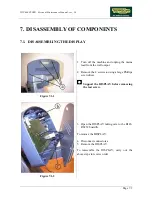
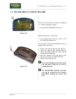
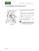
7.10. DISASSEMBLING THE BELT
Figure 7.10-1
Carry out the procedures described in paragraph
7.6. “Disassembling the right and left side
casings”.
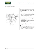
1. Back off nut
a
of belt tension rod
b
using a
17-mm wrench.
2. Back off dowel
d
with a 4-mm hex T-
wrench.
3. Move the alternator until BELT
c
can be
removed.
To facilitate the operation, the belt can
first be removed from the pulley.
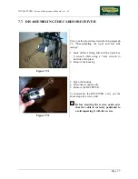
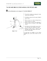
Figure 7.10-2
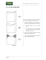
From both sides of the machine:
4. Use a marker pen to fix a reference index
between cam
e
and the machine frame to
facilitate readjustment during reassembly.
5. Unscrew the 2 screws
f
which fix the cam to
the machine frame, using a 4-mm hex T
wrench.
6. Disassemble the left hand cam.
The 2 cams are different: the one on the
left is threaded, the one on the right is
not.
Continued on following pages
→
Summary of Contents for Top 600 XTPRO
Page 1: ...SERVICE MAINTENANCE MANUAL REV 2 0...
Page 2: ......
Page 4: ......
Page 8: ...TOP 600 XTPRO Service Maintenance Manual rev 2 0 Page iv Page intentionally left blank...
Page 18: ...TOP 600 XTPRO Service Maintenance Manual rev 2 0 Page 2 8 Page intentionally left blank...
Page 26: ...TOP 600 XTPRO Service Maintenance Manual rev 2 0 Page 4 2 Page intentionally left blank...
Page 58: ...TOP 600 XTPRO Service Maintenance Manual rev 2 0 Page 7 18 Page intentionally left blank...
Page 70: ...TOP 600 XTPRO Service Maintenance Manual rev 2 0 Page 9 6 Page intentionally left blank...
Page 82: ......
Page 83: ...TOP 600 XTPRO Service Maintenance Manual rev 2 0 Page intentionally left blank Page 11 1...
Page 84: ......
Page 93: ......