background image

TRANSPORT PC 

PRO MAGNETIC RECUMBENT BIKE 

ITEM NO.: 26690 


OWNER’S MANUAL


IMPORTANT: Read all instructions carefully before using this product.    Retain this 
owner’s manual for future reference. 

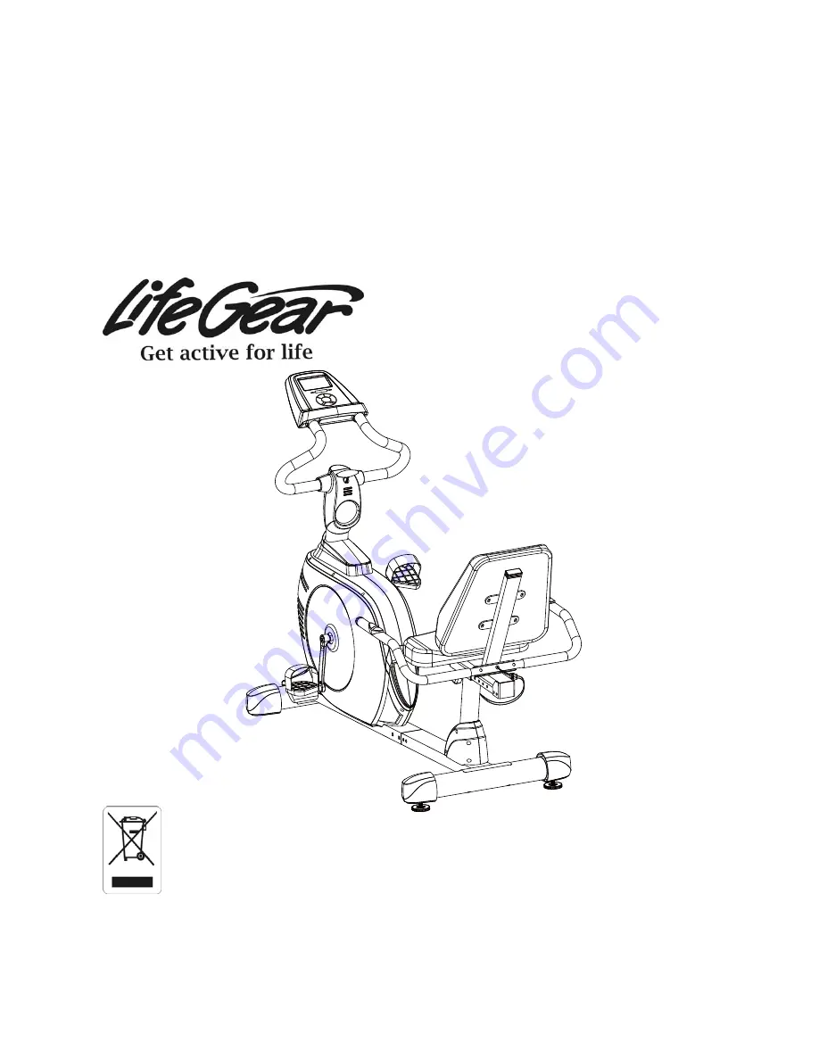
The specifications of this product may vary from this photo, subject to change without notice. 

2013, Oct.


Summary of Contents for 26690

Page 1: ...EM NO 26690 OWNER S MANUAL IMPORTANT Read all instructions carefully before using this product Retain this owner s manual for future reference The specifications of this product may vary from this photo subject to change without notice 2013 Oct ...

Page 2: ... 2 IMPORTANT SAFETY INSTRUCTIONS 3 PARTS LIST 4 HARDWARE PACKING LIST 6 TOOLS 6 OVERVIEW DRAWING 7 ASSEMBLY INSTRUCTIONS 8 OPERATING THE COMPUTER 16 ADJUSTMENTS 23 MAINTENANCE 21 TROUBLESHOOTING 21 WARM UP AND COOL DOWN ROUTINE 22 ...

Page 3: ...r repairing free of charge any parts which may prove to be defective under normal home use This warranty does not include any damage caused by improper operation misuse or commercial application From the date of purchase the frame is warranted to be free from defects for 1 one year This warranty is offered only to the original owner and is not transferable Proof of purchase is required When orderi...

Page 4: ...hould any problems arise discontinue use and consult your local dealer 6 Do not use the equipment outdoors 7 This equipment is for household use only It is not a commercial model 8 Only one person at a time should use this equipment 9 If you feel any chest pains nausea dizziness or short of breath you should stop exercising immediately and consult your physician before continuing 10 Care should be...

Page 5: ... 035 Nut M10x1 25 2 011 Hand Pulse Sensor Extension Wire B 1000mm 1 036R Right Crank 1 012 Computer Extension Wire C 1000mm 1 036L Left Crank 1 013 Front Post Ø76x1 5 1 037 Spring Clip Ø17 2 014 Bolt M8x45 2 038 Belt Pulley Ø260J6 1 015 Front Handlebar T Knob M8x75 1 039 Screw ST2 9x12mm 2 016 Spacer Ø12x1 5x50 1 040 Sensor with Wire 750mm 1 017 Front Main Frame 1 041 Belt Pulley Shaft 1 018 Bolt ...

Page 6: ...Right Rear Main Frame Cover 1 079 Washer Ø6xØ18x1 5t 9 060L Left Rear Main Frame Cover 1 080 Bolt M6x15 8 061 Hand Pulse Sensor Extension Wire A 1000mm 1 081 Seat Cushion 1 062 Bearing 6003ZZ 2 082 Back and Seat Support Bracket 1 063 Adjustable Leveler M10 2 083 Backrest and Seat Support Bracket End Cap 1 064 Nut M10 2 084 Back Cushion 1 065 Carriage Bolt M8x90mm 2 085 Computer Extension Wire A 60...

Page 7: ...lips Screwdriver S10 S13 S14 S15 1 PC Allen Wrench S6 1 PC 4 Screw ST4 2x20mm 1 PC 9 Screw ST2 9x16mm 8 PCS 25 Bolt M8x90mm 2 PCS 65 Carriage Bolt M8x90mm 2 PCS 68 Washer Ø20xØ8x2 0t 6 PCS 69 Cap Nut M8 4 PCS 14 Bolt M8x45 2 PCS 53 Washer Ø16xØ8x1 5t 2 PCS ...

Page 8: ...63 65 28 31 61 72 6 67 69 60R 76 78 64 60L 58 57 56 73 18 52 47 51 66 4 80 81 32 27 53 55 68 59 74 75 59 48 49 50 18 68 54 79 79 1 22 34 35 36L 34 35 36R 38 41 42 32 43 45 10 86 86 19 10 85 85 87 87 85 87 88 89 46 72 61 11 12 11 75 8A 4 9 9 53 53 6 70 71 8B 37 62 23 32 31 2 62 37 18 75 76 4 77 3 79 53 69 68 14 12 19 18 53 18 4 ...

Page 9: ...rovided Connect the Hand Pulse Sensor Extension Wire A 61 from the Rear Main Frame 67 to the Hand Pulse Sensor Extension Wire B 11 from the Front Main Frame 17 Attach the Rear Main Frame 67 into the Front Main Frame 17 with two M8x30mm Bolts 73 four M8x15mm Bolts 18 and six Ø20xØ8x1 5t Washers 2 that were removed Tighten bolts with the S6 Allen Wrench provided Allen Wrench S6 Tool 17 61 73 18 11 2...

Page 10: ...Rear Main Frame 61 and align bolt holes Attach the Rear Stabilizer 27 onto the rear curve of the Rear Main Frame 61 with two M8x90mm Carriage Bolts 65 two Ø20xØ8x2 0t Washers 68 and two M8 Cap Nuts 69 Tighten cap nuts and bolts with the Multi hex Tool with Phillips Screwdriver provided Install two M10 Adjustable Levelers 63 onto the Rear Stabilizer 27 Hardware Tool Multi Hex Tool with Phillips Scr...

Page 11: ... turn the pedal shaft in the clockwise direction doing so will strip the threads Tighten the pedal shaft of Left Foot Pedal 29L with the Multi Hex Tool with Phillips Screwdriver provided Insert pedal shaft of Right Foot Pedal 29R into threaded hole in Right Crank 36R Turn the pedal shaft by hand in the clockwise direction until snug Tighten pedal shaft of Right Foot Pedal 29R with the Multi Hex To...

Page 12: ...ing Tube 66 into the Bushings 72 of the Rear Main Frame 67 Attach the Seat Sliding Tube 66 to the Back and Seat Support Bracket 82 with eight M8x15mm Bolts 18 and eight Ø16xØ8x1 5t Washers 53 that were removed Tighten bolts with the S6 Allen Wrench provided Adjust the seat position and insert the Round Knob 71 and Triangle Knob 70 Turn the Round Knob 71 and Triangle Knob 70 in the clockwise direct...

Page 13: ...ire B 11 and Computer Extension Wire C 12 from the Front Main Frame 17 to the Hand Pulse Sensor Extension Wires C 10 and Computer Extension Wire B 86 from the Front Post 13 Insert the Front Post 13 onto the tube of the Front Main Frame 17 and secure with four M8x15mm Bolts 18 and four Ø8 Curve Washers 19 that were removed Tighten bolts and curve washers with the S6 Allen Wrench provided Slide the ...

Page 14: ...wdriver provided Attach the Rear Handlebar 78 onto the Back and Seat Support Bracket 82 with two M8x45 Bolts 14 two Ø20xØ8x2 0t Washers 68 two Ø16xØ8x1 5t Washers 53 and two M8 Cap Nuts 69 Tighten bolts and cap nuts with the Multi Hex Tool with Phillips Screwdriver and S6 Allen Wrench provided Connect the Hand Pulse Sensor Wires 75 from the Rear Handlebar 78 to the Hand Pulse Sensor Extension Wire...

Page 15: ...ont Handlebar 7 in desired position and fasten Front Rear Decorative Covers for Front Post 8A 8B M8x75 Front Handlebar T Knob 15 and Ø12x1 5x50 Spacer 16 onto clamp and tighten Front Rear Decorative Covers for Front Post 8A 8B with one ST4 2x20mm Screw 4 and eight ST2 9x16mm Screws 9 Tighten screws with the Multi Hex Tool with Phillips Screwdriver provided NOTE M8x75 Front Handlebar T Knob should ...

Page 16: ...1 onto the top end of the Front Handlebar 7 with two ST4 2x20mm Screws 4 that were removed Tighten screws with a Multi Hex Tool with Phillips Screwdriver provided 9 AC Adapter Installation Plug one end of the AC Adapter 77 into the power jack of the Power Supply Wire 89 on the front of the Right Shroud 33R Before plugging in make sure to check carefully the specifications on the Adapter Plug the o...

Page 17: ...NDER HEIGHT WEIGHT and AGE BODY FAT Press the BODY FAT button to select the PROGRAM 19 RECOVERY The Pulse Recovery is for personal orientation and compares the approximate pulse rate before and after training You will notice that your fitness will improve with regular exercise The Pulse Recovery feature is to be used directly after your workout To use this function 1 Grip the handlebar sensors wit...

Page 18: ... PROGRAM 19 LEVEL Indicates the level of loading selected from LEVEL 1 to LEVEL 16 GENDER Indicates the gender Male or Female selected TIME BMR HEIGHT WEIGHT AGE Display Indicates only one functional value of TIME BMR HEIGHT WEIGHT or AGE displayed depending on the programs SPEED K M RPM BMI Display Indicates only one functional value of SPD RPM BMI or K M displayed depending on the programs ...

Page 19: ...T or CAL displayed depending on the programs T H R PULSE Display Indicates only one functional value of T H R TARGET HEART RATE or PULSE displayed depending on the programs LOADING Profiles There are 10 intervals of loading bars and 8 bars in each interval Each intervals represents 3 minutes workout without the change of TIME value and each bar represents 2 levels of loading ...

Page 20: ...er are for exercise purpose only not for medical purpose Programs Selection There are 20 programs including 1 Manual Program 9 Pre set Programs 4 User Setting Programs 1 WATT Control Program 4 Heart Rate Control Programs and 1 Body Fat Program Program Graph Each graph shown is the profile of the loading in each interval With the value of TIME counting up each interval is 3 minutes that all the col...

Page 21: ...20 ...

Page 22: ...n to select TIME DISTANCE or CALORIES for target pre setting Then press the UP or DOWN button to adjust the values User may exercise with different level of loading in different intervals as the profiles show After pressing the START STOP button to exercise user may exercise in any desire level by pressing the UP or DOWN button User Setting Program PROGRAM 10 to PROGRAM 13 are the user setting pro...

Page 23: ... R Then press the UP or DOWN button to adjust the values User may setup a TARGET H R to exercise After pressing the START STOP button to exercise please also hold both two hands on handlebar grip sensors during exercise The computer will adjust the level of loading according to the heart rate detected For example the level of loading may increase while the heart rate detected is lower than TARGET ...

Page 24: ...from the rear main frame Turn the round knob in a counterclockwise direction until it can be pulled out Pull out the round knob and then slide the back and seat support bracket back or forth direction to the suitable position Lock the back and seat support bracket in place by releasing the round knob and sliding the back and seat support bracket back or forth slightly until the round knob pops dow...

Page 25: ...rn the adjustable leveler on the rear stabilizer as needed to level the recumbent bike There is no display on the computer console Remove the computer console and verify the wires that come from the computer console are properly connected to the wires that come from the front handlebar There is no heart rate reading or heart rate reading is erratic inconsistent 1 Make sure that the wire connection...

Page 26: ... of your entire exercise routine The WARM UP is an important part of any workout It should begin every session to prepare your body for more strenuous exercise by heating up and stretching your muscles increasing your circulation and pulse rate and delivering more oxygen to your muscles COOL DOWN at the end of your workout repeat these exercises to reduce soreness in tired muscles HEAD ROLLS Rotat...

Page 27: ...ADRICEPS STRETCH With one hand against a wall for balance reach behind you and pull your right foot up Bring your heel as close to your buttocks as possible Hold for 15 counts and repeat with left foot INNER THIGH STRETCH Sit with the soles of your feet together and your knees pointing outward Pull your feet as close to your groin as possible Gently push your knees toward the floor Hold for 15 cou...

Page 28: ...ean against a wall with your left leg in front of the right and your arms forward Keep your right leg straight and the left foot on the floor then bend the left leg and lean forward by moving your hips toward the wall Hold then repeat on the other side for 15 counts TOE TOUCHES Slowly bend forward from your waist letting your back and shoulders relax as you stretch toward your toes Reach as far as...

Reviews: