background image

Contrast 

– display contrast.

Week Timer

Fig 10

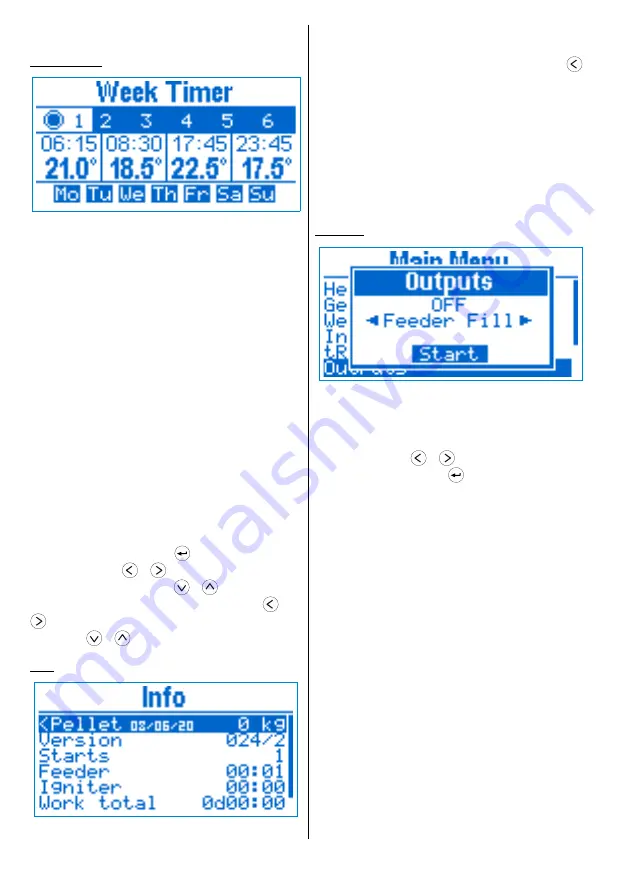
Week timer

Using the week timer, the user can specify a 

temperature for a particular time interval of the day 
for a given day of the week. It consists of 6 programs, 
each one having 4 timers that specifies time and 
temperature. The time of every next timer must be 
after the previous one, as a value of 

--:--

 means 

that the timer is not active. For example the timer 
configuration on 

Fig 11

 specifies the following 

temperatures and periods:

07:45 - 08:44 

21.0°C

08:45 - 17:44 

18.5°C

17:45 - 23:44 

22.5°C

23:45 - 07:44 

17.5°C

Every program can be active and applied to 

specific days of the week. In case more than one 
program is active for a given day of the week, the 
higher priority program is the one with bigger 
number.

Use the navigation buttons to select the current 

element you want to edit (program, time, 
temperature and day of week). Parameter editing is 
initiated by pressing button 

. While editing time, 

using the buttons 

 / 

 you decrease / increase 

the time by

 15 min

, as with 

 / 

 by 

1 hour

While editing temperature, using the buttons 

 /

 you decrease / increase the temperature by

 0.5 

°C, as with 

 / 

 by 

°C.

Info

Fig 11

Information

On this screen usage information is displayed:

Pellet

 – counter for the pellets burned from 

the last reset. In order to reset it, hold the button 


until you hear a sound signal. The counter is reset 
and the date is set to the current one.

Version

 – firmware version

Starts

 – controller power on count

Feeder

 – total feeder work time (HH:MM)

Lighter

 – total lighter work time (HH:MM)

Work total

 – device total work time 

(DddHH:MM)

First Start

 – date of first start

Outputs

Fig 12

Outputs

You can manually control the outputs 

Feeder

 and 

Fan

. This is only possible if the device is in 

OFF


mode.

Use the buttons 

 / 

 to choose the output you

want to control and press 

 to start / stop it. When 

an output is activated, a 4 min timer will stop it 
automatically when it expires.

Feeder Fill

The Feeder Fill function is used when the device is 

first powered on, or if the pellets have run out during
normal operation.

In case the feeder is empty, turn it on until some 

pellets start coming down in the work area. If the 
feeder is not full, then during the ignition phase less 
pellets will be fed, which may lead to ignition failure.

Fan

Fan function can be used for cleaning the burning 

chamber from ashes.

6

Using the device

Summary of Contents for tPell

Page 1: ...tPell Pellet Combustion Controller Version 24 06 20...

Page 2: ...tings 5 Week Timer 6 Info 6 Outputs 6 Date Time 7 Errors Actions 7 Principle of operation 8 Work mode 8 ON AUTO 8 OFF 8 States 8 Clean 8 Ignition 8 Kindle 8 Burn 8 Purge 8 Shutdown 9 Wait 9 Service pa...

Page 3: ...mostat on or off if used Current temperature the measured temperature of the heated object Power the current operating power when burning in kW or relative units Fumes fan revolutions of the fan in Fe...

Page 4: ...In AUTO mode the temperature is fixed by the week timer or the external thermostat Quick menu Fig 5 Quick menu To access the Quick menu press the button from the Main screen For navigation use the but...

Page 5: ...press to save the change or to cancel the modification and revert to the previous value Heating Fig 8 Heating Boiler Temp boiler temperature set point The power is modulated in order to achieve the te...

Page 6: ...decrease increase the temperature by 0 5 C as with by 2 C Info Fig 11 Information On this screen usage information is displayed Pellet counter for the pellets burned from the last reset In order to re...

Page 7: ...creen title in brackets Errors 6 the number of the registered errors is shown Press over selected element to get detailed information about it To switch between views use the buttons Errors The error...

Page 8: ...by monitoring the temperature of flue gases or the flame intensity depending on configuration On successful ignition it passes to the next state If the ignition time runs out before ignition is detec...

Page 9: ...e state However the device will automatically transition to ON mode when the system needs to generate heat The device is in standby awaiting for some of the heated objects to need heating When all the...

Page 10: ...pause Feeder run All parameters listed below that set the feeder time have the meaning of Feeder Fan Max Maximum revolutions per minute of the fumes fan It is used to calculate the percents that set...

Page 11: ...Turn on temperature Pump Min Temp Pump Hyst Turn off temperature Pump Min Temp Pump Hyst Wait DHW ON Temperature difference below the set temperature in order to exit from Wait state Wait DHW OFF Temp...

Page 12: ...e specified the shutdown is started Wait Temp ON Difference between the current and set temperature under which the device immediately transitions from Wait to Burn state Wait Temp OFF Difference betw...

Page 13: ...ignition Exceeding this temperature raise is considered for successful ignition Light Level Light sensor level exceeding it is considered for successful ignition Feeder2 Secondary feeder work time in...

Page 14: ...alue of the parameter is OFF Purge Period Purge period When the device is in Burn state and the set time expires it transitions to Purge state Upon completion it returns back to Burn state The minimum...

Page 15: ...ted and saved After changing the service password you will be asked again for it in order to access the service menu Stop Work Fig 18 Stop Work The device can be forced to stop ignoring the conditions...

Page 16: ...g stopped In Burn state a loss of flame is detected according to the flue gases temperature or light intensity Power failure The power was cut for time exceeding the recovery time Feeder blocked The c...

Page 17: ...ture sensor room temperature thermostat NTC 10K t4 Temperature sensor DHW Light sensitive i1 Light sensor flame intensity Active level GND i2 Hall sensor for fan revolutions counting i3 Capacitive ind...

Page 18: ...Fig 20 Connection 18 Connection...

Page 19: ...h square opening sized 128 x 57 mm To mount the controller first unscrew the mounting bracket then put the controller in the opening Fix it in place by putting the bracket on the back side and fasten...

Page 20: ...term is 24 months from date of sale The guarantee is not valid in following cases Incorrect installation Attempts to make repairs and or modifications of equipment by the customer Visible damages of...

Reviews: