


Installation and connection – DL bus
15
Data link for DL bus
The DL bus has only 2 wires:
DL
and
GND
(sensor earth). The DL bus itself supplies the power supply
for the DL bus sensors.
Cables can be routed with a star topology or in series (from one device to the next).
Any cable with a cross-section of 0.75 mm² up to 30 m in length can be used as a
data link
. Over 30
m, the use of a shielded cable is recommended, increasing the permissible cable length to 100 m.
Long cable conduits routed closely next to each other for mains and data links result in faults being
induced into the data link from the mains. We therefore recommend a minimum clearance of 20 cm
between two cable conduits or the use of screened cables.
Use separate, screened cables when capturing data from two controllers with a single datalogger.
Never run the data link together with a CAN bus cable in the same conduit.
Bus load from DL sensors
A 2-pole cable provides
both
the power supply and the signal transfer from DL bus sensors. An ad
-
ditional power supply by means of an external power supply unit (such as with the CAN bus) is not
possible.
Take the "
bus load
" into consideration as sensors have a relatively high current demand:
The CAN-EZ3 energy meter provides a maximum bus load of
100 %
. The bus loads of the electronic
sensors are listed in the technical data of the relevant sensors.
Example
: The FTS4-50DL electronic sensor has a bus load of
25 %
. Consequently, up to four FTS4-
50DL sensors can be connected to the DL bus.
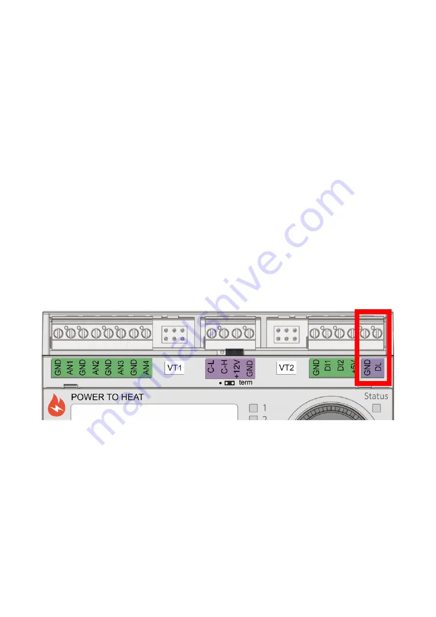
Terminal diagram, DL bus data link
Summary of Contents for CAN-EZ2
Page 5: ......
Page 62: ...62 Messages This menu item displays activated messages Example A message is active...
Page 98: ......
Page 99: ......


