background image

AIMA3000.FT5P Product User Manual

Technetix Group Limited

[email protected] 

 technetix.com

May/2016 - Version 1.0

45

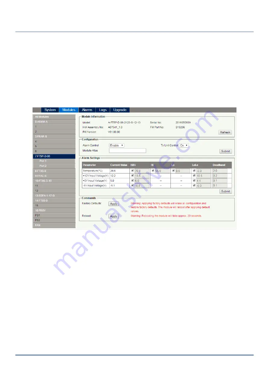
6.4 Restoring Factory Defaults

Loading factory default can restore the device to the factory default setting.

Detailed operations:

Click 

"Modules"

 tab and click the module to be configured as the page shown in 

Figure 6-11

. Click 

"Apply"

 button in 

Factory Default section. When finished, the device configuration will be reset. For more detailed factory reset information, 
please refer to the factory restore and upgrade configuration parameters table as in 

Table 6-6

.

Figure 6-11

Note: 

All the powers displayed on the webpage are total power. 

Summary of Contents for AIMA3000.FT5P

Page 1: ...May 2016 Version 1 0 AIMA3000 FT5P 1550 nm Forward Transmitter Performance Product User Manual ...

Page 2: ...AIMA3000 FT5P Product User Manual Technetix Group Limited sales technetix com technetix com May 2016 Version 1 0 2 AIMA3000 FT5P 1550 nm Forward Transmitter Performance Product User Manual ...

Page 3: ...lock Diagram 12 3 5 Order Details 13 4 Module Characteristics 15 4 1 Module Appearance and Port Layout 15 4 1 1 Overview 15 4 1 2 Front Panel Layout 16 4 1 3 Rear Panel Layout 18 5 Installation 20 5 1 Preparatory Work for Installation 20 5 2 Unpacking 20 5 3 Module Installation 21 5 4 Connecting Optical Cables 22 5 4 1 Using the Sliding Fibre Guide 22 5 4 2 Using the Fibre Tray 24 5 4 3 Cleaning t...

Page 4: ...creen 31 6 1 1 Confirming Input Signal 34 6 1 2 Alarm Status Pages 35 6 1 3 Module operating voltage and temperature alarm 36 6 1 4 Module Port Alarms 37 6 1 5 Alarm Monitoring Configuration 38 6 1 6 Input Output Status Monitoring 40 6 2 Logs Management 43 6 3 Device Upgrade 44 6 4 Restoring Factory Defaults 45 6 5 Reboot 47 7 Troubleshooting 48 8 Declaration of Conformity 50 ...

Page 5: ... other components 5 Installation Installation procedure 6 Module Configuration Alarms Web management configuration instructions 7 Troubleshooting 8 Product Warranty 9 Declaration of Conformity 1 2 Related Documentation The following documents may be used in conjunction with this manual Technetix AIMA3000 Product User Manual Technetix AIMA ASMM Product User Manual AIMA3000 NMS Web Management System...

Page 6: ...ed in this manual Asterisk Points marked with an asterisk means there is a corresponding note on the page 1 4 Technical Support If you need help in the process of setting up and maintaining an FT5P please contact Technetix s technical support staff Europe Technetix BV Kazemat 5 NL 3905 NR Veenendaal P O Box 385 NL 3900 AJ Veenendaal The Netherlands Phone 31 318 58 59 59 Email customer service vdl ...

Page 7: ... inside the device DO NOT power up before the cover and the panels of the equipment are installed and the enclosure is closed Cleaning Only use a damp cloth for cleaning the front panel Use a soft dry cloth to clean the top of the unit DO NOT use any spray cleaners or chemicals of any kind Outage or overload requiring service and repairs Unplug the unit and refer the servicing to Technetix qualifi...

Page 8: ...l ITU frequency grids Technetix AIMA3000 FT5P series transmitter is designed for multi service operators MSOs to increase network capacity to satisfy an ever growing subscriber demand for more bandwidth The FT5P can be used with Erbium Doped Fibre Amplifiers EDFA in short haul Fibre to the Home FTTH applications and medium haul set ups with a high RF performance of up to 60 km All FT5P models can ...

Page 9: ...o 60 kilometers without any dispersion compensation required High SBS suppression level to allow launch power up to 20 dBm Automatic gain control AGC for a consistent optical modulation index OMI Automatic laser power control for consistent optical output Comprehensive alarm reporting and monitoring Remote firmware upgrade and auto upload download of configuration files through ASMM web interface ...

Page 10: ... test point 20 dB 1 dB relative to laser input Port to port Isolation 50 dB narrowcast to broadcast RF input connectors Single 2 x GSK type female 1 for NC 1 for BC Double 4 x GSK type female 2 for NC 2 for BC RF test points Single 1 x Mini SMB 3 Dual 2 x Mini SMB 3 Alarms and laser status Front Panel LEDs SNMP traps Link Performance 4 MER 38 dB BER 1E 9 General Power supply Powered via AIMA3000 b...

Page 11: ...Version 1 0 11 Notes 1 The factory default ITU optical channel is 33 2 dBuV 60 dBmV 3 One mini SMB connectors on front panel to measure RF input before the laser transmitter 4 MER and BER are tested with 117 QAM256 301 25 MHz 997 25MHz All are measured thought EDFA launch power of 20 dBm 20 km of fibre ...

Page 12: ... technetix com May 2016 Version 1 0 12 3 4 Block Diagram Table 3 1 FT5P Block Diagram Glossary Figure 3 1 Block diagram FT5P Parameters Glossary NC Narrowcast BC Broadcast ATTEN Attenuator 20 dB OMI TP 20 dB Test Point TO BACK PLANE AND COMMS Data Bus CPU Central Processing Unit ...

Page 13: ...Bm 4 mw 07 7 dBm 5 mw 08 8 dBm 6 3 mw 09 9 dBm 8 mw 10 10 dBm 10 mw 11 11 dBm 12 6 mw 12 12 dBm 15 8 mw 13 13 dBm 20 mw 14 14 dBm 25 mw 15 15 dBm 31 6 mw 16 16 dBm 39 8 mw 17 17 dBm 50 12 mw 06 6 dBm 4 mw W SBS Suspension 17 17 dBm 20 20 dBm X Wavelength 2 21 192 1 THz 1560 61 nm 22 192 2 THz 1559 79 nm 23 192 3 THz 1558 98 nm 33 193 3 THz 1550 92 nm 34 193 4 THz 1550 12 nm 35 193 5 THz 1549 32 nm...

Page 14: ...ersion 1 0 14 Note 1 Default 5 dBm contact Technetix Representatives for order detailed 6 15 dBm output power 2 Default spacing is 100 GHz For other wavelength configurations not listed please contact Technetix 3 Standard option Contact a Technetix Sales Representative for availability of other options ...

Page 15: ...User Manual Technetix Group Limited sales technetix com technetix com May 2016 Version 1 0 15 4 Module Characteristics 4 1 Module Appearance and Port Layout 4 1 1 Overview Front Panel Rear Panel Figure 4 1 Module Appearance ...

Page 16: ...AIMA3000 FT5P Product User Manual Technetix Group Limited sales technetix com technetix com May 2016 Version 1 0 16 4 1 2 Front Panel Layout Figure 4 2 FT5P Front Panel Layout ...

Page 17: ...r Major Alarm Red 3 LSR1 LED Laser 1 Status Indicator ON Green OFF Red Major Alarm Red 4 LSR1 TP Laser 1 Input Test Point 5 LSR2 LED Laser 2 Status Indicator ON Green OFF Red Major Alarm Red 6 LSR2 TP Laser 2 Input Test Point 7 Orange tab retaining clip Used to plug and anchor the module The tab retaining clip will pop up after pressing the release and plug module 8 OPT OUT 1 Optical output 1 9 OP...

Page 18: ...AIMA3000 FT5P Product User Manual Technetix Group Limited sales technetix com technetix com May 2016 Version 1 0 18 4 1 3 Rear Panel Layout Figure 4 3 Rear Panel Layout ...

Page 19: ...ear Panel Functions Serial Number Item Description 1 NC1 IN Narrowcast RF input 2 BC1 IN Broadcast RF input 3 NC2 IN Narrowcast RF input 4 BC2 IN Broadcast RF input 5 Air Vent Air vent allowing air to flow out of the module 6 Multi pin connector Power and communication port 7 Placement Pin Used to position the module in the chassis ...

Page 20: ... representative Necessary equipment and tools for installation Table 5 1 Necessary equipment and tools for installation Tools Modules Description Phillips screwdriver PH1 PH2 For use with the AIMA3000 chassis FT5P Module The module to install into the AIMA3000 chassis No Description Qty 1 FT5P module 1 2 Individual test sheet Certificate of Performance 1 5 2 Unpacking Unpack the module Keep the pa...

Page 21: ...until it reaches the multi pin connector DO NOT use excessive force when inserting the module but ensure the RF connectors at the rear of the module are securely connected with the chassis s RF connectors CAUTION The module MUST be installed correctly to ensure a proper connection of the module s multi pin connector and the backplane Tip When inserting the module into the guide rails vertically ti...

Page 22: ...the AIMA module fasten the spring loaded mounting screw Only use fingers to fasten the mounting screw DO NOT use a screwdriver 5 4 Connecting Optical Cables For the convenience of the user the AIMA3000 Chassis has a Sliding Fibre Guide to help the operator to arrange the cables For the specific steps to connect the fibre please refer to the instructions in section 5 4 1 5 4 1 Using the Sliding Fib...

Page 23: ...Product User Manual Technetix Group Limited sales technetix com technetix com May 2016 Version 1 0 23 2 Then pull the panel forward 3 Then lift up the handle and slide the fibre guide out of the front of the chassis ...

Page 24: ...hat the optical fibre tail does not become trapped or pulled tightly Fibre clip at rear for up to two connectors Handle at front 5 4 2 Using the Fibre Tray All optical fibres must be organised in a tidy manner in the chassis s fibre tray which provides enough space for up to 64 optical fibres This allows for easy positioning and future replacement of optical fibres Along the front of the chassis t...

Page 25: ...netix Group Limited sales technetix com technetix com May 2016 Version 1 0 25 2 Use the Fibre Guide Tool to organise the cables and wires in the fibre tray to prevent tangles and the blocking of the guide rails Fibre Tray Area PSU Cut outs ...

Page 26: ...ampened with a static dissipative solvent to clean the angled surface Dry the surface using a dry lint free cloth To clean the front panel optical port use a special lint free swab that is designed for this purpose Dampen it with a static dissipative solvent Apply slight pressure to the internal angled surface of the optical port while rotating the swab 90 degrees back and forth You may need to re...

Page 27: ...dule LEDs When the module has been installed if the chassis is powered all LED indicators on the front panel will show a blinking green light indicating the module is initiating If the input signal and output signal are normal the STAT LED indicator will cease to blink in about 5 seconds and remain constant green afterwards At the same time the LSR LED indicators will also remain constant green wh...

Page 28: ...hnical specifications Before testing the optical power meter must be calibrated Before measuring optical signals verify the interfaces are clean and undamaged CAUTION The device output optical power measurement procedure and regular maintenance must be performed by highly trained personnel All procedures and maintenance must be comply with the necessary safety precautions indicated with using FT5P...

Page 29: ...output power with a cleaned optical patch cord and a calibrated optical power meter Record the optical output level Connect a cleaned patch cord to the fibre output and to the relevant optical distribution frame ODF panel 4 With a laptop connected to the ASMM module s network or an Android device connected to the front of the ASMM module s USB port in host mode Select the port for the transmitter ...

Page 30: ...oduct User Manual Technetix Group Limited sales technetix com technetix com May 2016 Version 1 0 30 6 Confirm that the Alarm Control is enabled Check the required selection and click on Submit to enable disable alarms ...

Page 31: ...etails and network setup please refer to the AIMA ASMM user manual If the same module is reinserted in the same slot the ASMM will restore the previous settings if the module is set to Auto Download the configuration 6 1 Port Configuration screen After logging in to the AIMA ASMM controller select the Modules tab and then the FT5P to configure one of the FT5P transmitters After selecting FT5P the ...

Page 32: ...tion screen Laser Output Control Modulation Mode Input AGC Mode Wavelength Set Broadcast MGC Norrowcast MGC OMI Offset SBS Control and Alarm Settings become available For proper RF settings with different RF channel loads see the example calculations shown in 6 1 1 All transmitters have independent settings and they need to be adjusted separately ...

Page 33: ...r Configuration Input AGC Mode Enable AGC ON Automatic Gain Control OFF Manual Gain Control Wavelength Set Laser Output Control Laser output control On Off OMI offset Change Factory Default OMI Value based on individual needs 3 3 dB Modulation Mode Modulation mode CW continuous wave for Factory Configuration Modulated modulating signal for customers The default setting is modulated CW Modulated Br...

Page 34: ...r of channels On Figure 6 3 the interface displays the Broadcast Input Power Narrowcast Input Power and the RF Composite Input Power The operator can calculate the power per channel When the different channels and levels are configured for the FT5P the operator can also calculate the appropriate gain adjustment to ensure the total RF power for the laser All alarm information is monitored by the AS...

Page 35: ...May 2016 Version 1 0 35 6 1 2 Alarm Status Pages Click the Alarms tab on the menu bar to display an overview of the alarm status of all the installed modules as shown in Figure 6 4 below The each module row has an alarm status indicator used to show Normal operation Green Alarms Red Figure 6 4 ...

Page 36: ...rmation By clicking on FT5P under Modules tab the operator can view the module temperature and power supply voltage alarms The operator can utilise the status indicators to judge whether the module is working properly The status has three conditions Normal Green Major Alarm Red Minor Alarm Amber Figure 6 5 Use the status indicators to determine if the module is working properly If the device is re...

Page 37: ...Click on one of the Port Tabs under the module on the left column as shown in Figure 6 6 On the module port page the operator can view the BC Input Power NC Input Power Laser Case Temperature Laser Output Power Laser Output and the Laser Bias Current alarms Status has three conditions Normal Green Minor Alarm Amber Major Alarm Red Figure 6 6 ...

Page 38: ...rol to Enable Disable Monitoring Function Temperature 12V 5V 5V Voltage Alarm Levels Management By default temperature 12 V 5 V 5V voltage alarms are all set to ON The check box as shown in Figure 6 7 controls the detection is set to ON or OFF When the check box is checked detection ON the texts in the text box are always grey the parameters cannot be changed The parameters instruction is shown in...

Page 39: ...0 39 Table 6 2 Modules Page Alarms Threshold Parameters Instruction Parameter Units HIHI HI Normal LO LOLO Dead Band Threshold changeable by user Default Alarm Enable Temperature oC 70 65 0 5 2 N ON 12V Input voltage V 13 5 12 10 5 0 2 N ON 5V Input voltage V 6 5 4 4 0 1 N ON 5V Input voltage V 4 4 5 6 0 1 N ON ...

Page 40: ...The customer can change the monitoring parameters All transmitters have independent settings and they need to be adjusted separately See Figure 6 8 Figure 6 8 Table 6 3 Port Page Alarms Threshold Parameters Instruction Parameter Units HIHI HI Normal LO LOLO Dead Band Threshold changeable by user Default Alarm Enable BC Input Power dBuV 106 8 101 8 85 8 80 8 1 Y ON NC Input Power dBuV 116 8 111 8 9...

Page 41: ...OFF either port Blinking ON all ports Green always RF Critical ALM RF Input Power is too high HiHi or too low LoLo STAT LSR1 LSR2 LSR3 LSR4 Red RF Warning ALM RF Input Power is higher Hi or lower Lo STA1T LSR1 LSR2 LSR3 LSR4 Amber Laser Critical ALM Laser Temperature is too high HiHi or too low LoLo STAT LSR1 LSR 2 LSR3 LSR4 Red Laser Bias Current is too high HiHi or too low LoLo Laser Output Powe...

Page 42: ...r OFF Power OFF All All OFF Initiating AM Power ON During Module Power ON All Green 2 times sec No Alarm Normal operation Normal All Green Upgrading AM Firmware AM Upgrading Module upgrade MODE AM Critical ALM Critical Alarm STAT Red AM Minor ALM Warning Alarm STAT Amber RF Critical High RF Major ALM RF Level High STAT Red RF Warning High RF Minor ALM RF Level Low STAT Amber AGC MGC AGC MGC Mode C...

Page 43: ...ed sales technetix com technetix com May 2016 Version 1 0 43 6 2 Logs Management The operator can view all the alarms of the modules in the chassis on the Logs Management page Click Logs to enter the Logs Management page Refer to Figure 6 9 below Figure 6 9 ...

Page 44: ...rocess At the same time you will be automatically redirected to the Network Management page The upgrade operation is then complete Figure 6 10 The upgrade file needs to be located on the PC that is connected to the ASMM The Web GUI above only supports the manual operation from a local PC The FT5P supports automated firmware updates and automatic backup restore features via TFTP when managed via Te...

Page 45: ...ing Detailed operations Click Modules tab and click the module to be configured as the page shown in Figure 6 11 Click Apply button in Factory Default section When finished the device configuration will be reset For more detailed factory reset information please refer to the factory restore and upgrade configuration parameters table as in Table 6 6 Figure 6 11 Note All the powers displayed on the ...

Page 46: ...ware Upgrade Alarm Control Enable Disable Enable Retained Tx Unit Control ON OFF ON Retained Laser Output Control ON OFF ON Retained Modulation Mode CW Modulated Modulated Retained Input AGC Mode ON OFF OFF Retained Broadcast MGC 6 0 0 0 0 Retained Narrowcast MGC 3 0 3 0 0 Retained OMI offset dB 3 0 3 0 0 Retained SBS Control Enable Disable Enable Retained Laser Output Status Alarm Enable Major En...

Page 47: ... 6 5 Reboot The module can be made to reboot remotely Detailed operations Click Modules tab click the corresponding FT5X module and click the Apply button in Reboot section Next click on Submit to confirm and then the module will automatically restart The configuration of the module will not be lost after rebooting ...

Page 48: ...Laser Output Power is higher Hi or lower Lo Check the laser s Output Power If the Output Power is normal please contact Technetix technical support Laser is shutdown Laser Output Status Alarm is set enable Minor Turn on the laser RF Input Power is higher Hi or lower Lo Adjust RF input signal LSR1 LSR2 LSR3 LSR4 is red Laser Temperature is too high HiHi or too low LoLo Check the laser s temperature...

Page 49: ... signal or adjust MGC to an appropriate value Laser Warning ALM or Laser shutdown Laser Output Status Alarm is set Enable Minor Check the laser s status STAT is red Operating environment Temperature is too high or too low Check the Fans or lower the room temperature If the temperature is normal please contact Technetix technical support 12V 5V 5V Input Voltage too high or too low Please contact Te...

Page 50: ...cturer s Name Technetix Manufacturer s Address Technetix Ltd Innovation House Technetix Business Park Albourne West Sussex BN6 9EB Product Name FT5P 1550 nm Forward Transmitter Performance Conforms to the following standards FCC FCC Part 15 Subpart B 2012 CE EN 50083 2 2012 EN 5504 2010 EN 61000 3 2 2006 A1 2009 A2 2009 EN 55022 2010 EN 61000 3 3 2008 RCM AS NZS CISPR22 2009 A1 2010 Pending ...

Page 51: ...technetix com May 2016 Version 1 0 ...

Reviews: