background image

18

Oct/2017 - V1

Technetix Group Limited

Product User Manual

AIMA-FT5E

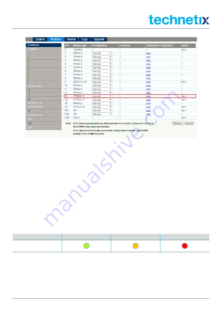
Figure 5-3 Module configuration details view and download/upload mode settings

5.2 Alarms

5.2.1 FT5E Module Alarms

Select 'Alarms' on the AIMA3000 configuration system interface and select the FT5E module from the module list on the 
left. The interface will open, as shown in Figure 5-4. The right side of the interface displays the alarm status details for the 
FT5E module and the ports listed under the FT5E module. Click on the port to see its alarm status details displayed in the 
white area on the right (see Chapter 5.2.2, Figure 5-5).
The FT5E module’s alarm status interface shows the current values of the module’s temperature,
+12V input voltage, +5V input voltage, and -5V input voltage, as well as the threshold values, blind spots, and status for 
alarms of different levels. Press 'Refresh' to refresh information about the alarm status for each parameter of the FT5E 
module. See Table 5-3 for indicator lights corresponding to alarms of different levels.

Table 5-3. Indicator lights for alarms of different levels

Normal (No Alarm)

Secondary Alarm

Main Alarm

Indicator light status

Summary of Contents for AIMA3000-FT5E

Page 1: ...AIMA3000 FT5E 1550 NM FORWARD TRANSMITTER ENHANCED Online Email customer service vdl technetix com Website technetix com Oct 2017 V1 Technetix Group Limited Product User Manual...

Page 2: ...kaging and Transportation 9 4 3 Installation and Wiring 9 4 3 1 Installation 9 4 3 2 FT5E Wiring 9 4 3 3 LED Indicator Lights 12 5 Module Configuration and Alarms 13 5 1 Module Configuration 13 5 1 1...

Page 3: ...device Do not power up before the cover and the panels of the equipment are installed and the enclosure is closed Cleaning Only use a damp cloth for cleaning the front panel Use a soft dry cloth to c...

Page 4: ...ual Technetix NMS3 EPSM Basic Inventory Management Technetix NMS3 EPSM Basic Alarm Management Technetix NMS3 EPSM Basic System Management Technetix NMS3 EPSM Basic Template Management 1 3 Technical Su...

Page 5: ...ts dual channel configuration It can be used in HFC 1550 nm optical transmission systems and effectively improves network performance The FT5E employs an advanced RF circuit design and a high quality...

Page 6: ...B Transmitter isolation 65 dB RF input connector 4 GSK female 2 for NC and 2 for BC RF test points Mini SMB 43 Alarms Front panel LEDs SNMP Traps Link Performance CNR CSO CTB MER BER NTSC QAM4 50 dB 5...

Page 7: ...ptical ports D Dual 2 W Optical output power per port 08 8 dBm 6 3 mw 09 9 dBm 8 mw 10 10 dBm 10 mw X Wavelength 21 192 1 THz 1560 61 nm 22 192 2 THz 1559 79 nm 23 192 3 THz 1558 98 nm 25 192 5 THz 15...

Page 8: ...Figure 3 1 FT5E block diagram Component Description NC 20 dB TP BC Attenuator Atten Gain Slope 20dB OMI TP OMI ADJ Pre D Total OMI To back panel and comms Connection chassis back panel module power s...

Page 9: ...p Limited Product User Manual AIMA FT5E 3 2 FT5E Module Structure 3 2 1 FT5E Module Appearance 3 2 2 FT5E Module Front Back Panel Layout Figure 3 2 FT5E module Figure 3 3 FT5E front panel layout Figur...

Page 10: ...1 dB 5 Channel 2 laser RF level test point 20 1 dB 6 Channel 2 narrowcoast input test point 20 1 dB 7 Button 8 Optical output port 1 9 Optical output port 2 10 Fastening screw No Component Descriptio...

Page 11: ...y the original packaging for transporting the FT5E as it has been specifically designed to protect this product 4 3 Installation and Wiring 4 3 1 Installation Conduct the following inspections after u...

Page 12: ...onfiguration system and ensure that the laser temperature bias current and output power are within the normal range If values are not within the normal range make adjustments according to the paramete...

Page 13: ...nel optical port use a special lint free swab that is designed for this purpose Dampen it with a static dissipative solvent Apply slight pressure to the internal angled surface of the optical port whi...

Page 14: ...ed components 4 3 3 LED Indicator Lights After the module is installed and connected to a power supply green indicator lights on the front panel indicate that the module is on If the input and output...

Page 15: ...Select the Modules option in the AIMA3000 configuration system interface Select the FT5E module from the module list on the left see Figure 5 1 The white area on the right side of the interface shows...

Page 16: ...etting Item Description Factory Defaults When the Apply button is pressed all FT5E settings are cleared and restored to default After this process is completed the module is automatically rebooted Reb...

Page 17: ...ng alarm is triggered When the values are between the Hi and Lo threshold values the alarm status is normal no alarm The secondary alarm is triggered if the Hi Lo threshold value is exceeded The main...

Page 18: ...er 2dB than Modulated Modulated modulated wave default Input AGC Mode On switches on the AGC mode Off switches off the AGC mode default OMI Offset Range 3 0 3 0 dB default 0 dB Broadcast MGC Range 10...

Page 19: ...ding Downloading Module Config Files Select Modules on the AIMA3000 configuration system interface Select All Modules in the module list on the left side as shown in Figure 5 3 Find the FT5E module in...

Page 20: ...FT5E module Click on the port to see its alarm status details displayed in the white area on the right see Chapter 5 2 2 Figure 5 5 The FT5E module s alarm status interface shows the current values of...

Page 21: ...T5E port alarm status interface shows the current values of BC input power NC input power RF composite input power laser temperature laser bias current laser output power and AGC status as well as the...

Page 22: ...he white area on the right side of the interface shows all alarm logs for the installed modules a maximum of 1000 logs can be displayed as shown in Figure 5 6 Use the First Page Page Up Page Down and...

Page 23: ...own in Figure 5 7 will appear Press Select File to search for and download the latest FT5E firmware Press Start Upgrade to upgrade the firmware Note Before upgrading the module download the latest mod...

Page 24: ...rt The optimal input values in the QAM environment are as follows 1 10dBmV ch 94 ITU T J 83 Annex A QAM 256 258MHz 994MHz 1206MHz DOCSIS 3 1 OFDM Centre 1100MHz 192MHz width 4k FFT Suggest reduce the...

Page 25: ...t power is normal but the alarm is still on contact Technetix technical support STAT Optical output power and bias current values are not within the normal range Contact Technetix technical support Po...

Page 26: ...etix Manufacturer s Address Technetix Ltd Innovation House Technetix Business Park Albourne West Sussex BN6 9EB Product Name OPSW Optical A B Protection Switch Conforms to the following standards FCC...

Page 27: ...Steady light Steady light Steady light Steady light Steady light Module port main alarm triggered Steady light Module port secondary triggered Steady light BC NC input 1 RF total power main alarm HiHi...

Page 28: ......

Reviews: