technetix AIMA-OPSW Product User Manual Download Page 27

24

Aug/2017 - V1

Technetix Group Limited

Product User Manual

AIMA-OPSW

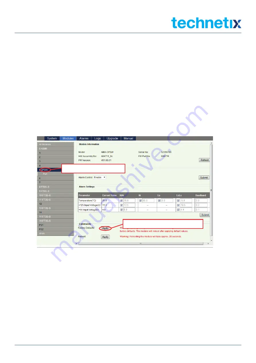
6.2 Restoring Factory Defaults

Loading factory default can restore the device to the factory default setting.

Detailed operations:

In the web interface, click the modules tab and click the module to be reconfigured on the left column of the interface 

(Figure 6-1)

. Click the 

Apply

 button in the Factory Default section. When finished, the device configuration will be reset. 

For more details about the factory default configuration please refer to the factory restore and upgrade configuration 
parameters table shown in 

Table 6-1

.

AIMA-OPSW

 Product User Manual


Pacific Broadband Networks 

18 January 2017 

Page 29 of 49 

6.2  Restore Factory Defaults 

Loading factory default can restore the device to the factory default settings. 

Detailed operations: 

In the web interface, click the modules tab and click the module to be reconfigured on the left column 
of the interface (

Figure 6-1

). Click the 

Apply

 button in the Factory Default section. When finished, the 

device configuration will be reset. For more details about the factory default configuration  please refer 
to the factory restore and upgrade configuration parameters table shown in 

Table 6-1

.  

Note:  

All the powers displayed on the webpage are total power.  


Figure 6-1


1 Click the module to be configured.


2 Click 

Apply

 to load factory default settings. 


Figure 6-1

Note: 

All the powers displayed on the webpage are total power.

Summary of Contents for AIMA-OPSW

Page 1: ...AIMA OPSW OPTICAL A B PROTECTION SWITCH Online Email customer service vdl technetix com Website technetix com Aug 2017 V1 Technetix Group Limited Product User Manual...

Page 2: ...5 Order Details 13 4 Module Characteristics 15 4 1 Module Appearance and Port Layout 15 4 1 1 Overview 15 4 1 2 Front Panel Layout 16 4 1 3 Rear Panel Layout 18 4 2 Technical Description 15 4 2 1 Blo...

Page 3: ...uration using a PC 15 6 1 2 Configuration using a Android device 16 6 2 Restore Factory Defaults 15 6 3 Reboot 15 6 4 Port Configuration 15 6 4 1 Revert Function 16 6 5 Module Appearance and Port Layo...

Page 4: ...o not power up before the cover and the panels of the equipment are installed and the enclosure is closed Cleaning Only use a damp cloth for cleaning the front panel Use a soft dry cloth to clean the...

Page 5: ...Module Configuration Alarms Web management configuration instructions 7 Troubleshooting 8 Product Warranty 9 Declaration of Conformity Appendix A Default Alarm Parameters Appendix B dB Conversion Tabl...

Page 6: ...sk Points marked with an asterisk means there are corresponding notes on the page 2 4 Technical Support If you need help in the process of setting up and maintaining an FT5X please contact Technetix s...

Page 7: ...computer a mobile device or through Technetix s NMSE management software 3 2 Product Key Features Plug and play with the AIMA3000 platform Three adjustable optical input levels to suit different optic...

Page 8: ...th optical safety shutter Alarms Front panel LEDs SNMP Traps Switching time 15 ms RF Performance Test port on the front panel RF power range1 0 30 dBmV ch 77 ch NTSC Switch accuracy of RF 1 dB RF Conn...

Page 9: ...iagram 3 5 Order Details A OPSW Y Z Optical A B Protection Switch Options Y Optical Connector Type S SC APC F FC APC L LC APC E E2000 APC Z Bandwidth 1G 45 1000 MHz Figure 3 1 OPSW Block Diagram Stand...

Page 10: ...7 Aug 2017 V1 Technetix Group Limited Product User Manual AIMA OPSW 4 Module Characteristics 4 1 Module Appearance and Port Layout 4 1 1 Overview Front Panel Rear Panel Figure 4 1 Module Appearance...

Page 11: ...8 Aug 2017 V1 Technetix Group Limited Product User Manual AIMA OPSW 4 1 2 Front Panel Layout Figure 4 2 OPSW Front Panel Layout...

Page 12: ...A light blinks once per second ON Green Minor Alarm Orange Major Alarm Red 4 OPT2 LED Input B status indicator if choosing B light blinks once per second ON Green Minor Alarm Orange Major Alarm Red 5...

Page 13: ...ar Panel Layout 4 1 3 Rear Panel Layout Table 4 2 OPSW Rear Panel Functions Item Number Item Description 1 Air vent Module air vent allowing air to flow out of the module 2 Multi pin connector Power s...

Page 14: ...agram Parameters Glossary OPT IN A also labeled InputB Optical input A OPT IN B also labeled InputA Optical input B OPT OUT Optical Output RF TP A RF A test port RF TP B RF B test port PD Detect A B A...

Page 15: ...and compared against the threshold parameters set by the administrator InputA is the default input In event of signal loss at InputA and only the signal at InputB is within the set parameters the OPSW...

Page 16: ...assis FT5X module The module to install into the AIMA3000 chassis No Description Qty 1 OPSW module 1 2 Product User Manual CD 1 3 Individual test sheet Certificate of Performance 1 5 2 Installation St...

Page 17: ...i pin connector DO NOT use excessive force when inserting the module but ensure the RF connectors at the rear of the module are securely connected with the chassis s RF connectors CAUTION The module M...

Page 18: ...onvenience of the user the AIMA3000 Chassis has a Sliding Fibre Guide to help the operator to arrange the cables For the specific steps to connect the fibre please refer to the instructions in section...

Page 19: ...16 Aug 2017 V1 Technetix Group Limited Product User Manual AIMA OPSW 2 Then pull the panel forward 3 Then lift up the handle and slide the fibre guide out of the front of the chassis...

Page 20: ...l does not become trapped or pulled tightly Fibre clip at rear for up to two connectors Handle at front 5 4 3 Using the Fibre Tray All optical fibres must be organised in a tidy manner in the chassis...

Page 21: ...Technetix Group Limited Product User Manual AIMA OPSW 2 Use the Fibre Guide Tool to organise the cables and wires in the fibre tray to prevent tangles and the blocking of the guide rails Fibre Tray Ar...

Page 22: ...dissipative solvent to clean the angled surface Dry the surface using a dry lint free cloth To clean the front panel optical port use a special lint free swab that is designed for this purpose Dampen...

Page 23: ...ctors will show a green light 5 6 Check Module LEDs After the input signal has been confirmed the optical power of the optical output port should be tested Use the optical power meter to test the outp...

Page 24: ...n also connect through a local network on a switch hub if both the module and user are on the same subnet 6 1 1 Configuration using a PC Manually configure your network interface card to have an IP ad...

Page 25: ...ngs menu Select More Settings in Wireless and Network settings and select Tethering and portable hotspot and enable USB Tethering After USB Tethering is enabled the word tethered will appear on the sc...

Page 26: ...192 168 42 129 2 Please disconnect the USB cable from the ASMM when resetting attaching or removing the ASMM for the chassis up your internet browser on your Android device Then type in 192 168 42 AS...

Page 27: ...Manual Pacific Broadband Networks 18 January 2017 Page 29 of 49 6 2 Restore Factory Defaults Loading factory default can restore the device to the factory default settings Detailed operations In the...

Page 28: ...configuration parameters table Parameters Configuration Factory Default Value After Software Upgrade Alarm Control ON OFF ON Retention Switch Mode Automatic Manual Automatic Retention Revert Enable ON...

Page 29: ...of the module will not be lost after rebooting AIMA OPSW Product User Manual Pacific Broadband Networks 18 January 2017 Page 31 of 49 6 3 Reboot The module can be rebooted remotely shown in Figure 6 2...

Page 30: ...2 for the modules configuration parameters in detail AIMA OPSW Product User Manual Page 32 of 49 18 January 2017 Pacific Broadband Networks 6 4 Port Configuration We recommend the operator learn the...

Page 31: ...view Port Information Please refer to Table 6 3 for a more detailed description AIMA OPSW Product User Manual Pacific Broadband Networks 18 January 2017 Page 33 of 49 Table 6 2 Modules Configuration P...

Page 32: ...ntrol Path A Path B Path A Path B Revert Enable Revert from B to A On Off Wait To Restore Time Change Factory Default OMI Value based on individual needs Wavelength 1270 00 nm 1630 00 nm Optical Input...

Page 33: ...be switched back to InputA from InputB The setup screen is shown in Figure 6 5 AIMA OPSW Product User Manual Pacific Broadband Networks 18 January 2017 Page 35 of 49 6 4 1 Revert Function To enable t...

Page 34: ...ee conditions Normal Green Light Minor Alarm Orange Light Major Alarm Red Light AIMA OPSW Product User Manual Page 36 of 49 18 January 2017 Pacific Broadband Networks 6 5 Alarms Monitoring All alarm i...

Page 35: ...ule operating voltage and temperature alarm By clicking on the corresponding module as shown in the following figure the module s alarm information will appear By clicking on OPSW under the Modules ta...

Page 36: ...us has three conditions Normal Green Minor Alarm Amber Major Alarm Red Figure 6 8 AIMA OPSW Product User Manual Page 38 of 49 18 January 2017 Pacific Broadband Networks 6 5 3 Module Port Alarms Click...

Page 37: ...able or disable the Monitoring Function 6 5 5 Temperature 12V 5V Voltage Alarm Levels Management By default the temperature 12 V and 5 V voltage alarms are all set to ON The check boxes shown in Figur...

Page 38: ...ttings check the boxes to toggle alarms The page is shown in Figure 6 10 below AIMA OPSW Product User Manual Page 40 of 49 18 January 2017 Pacific Broadband Networks 6 6 Input Output Status Monitoring...

Page 39: ...al High Warning High Normal Warning Low Critical Low Dead Band Modifiable Factory Default Path A Optical Input Power dBm 25 0 24 0 N A 11 0 10 0 0 5 Yes ON Path A RF Input Level dB V 55 9 53 9 N A 23...

Page 40: ...ow navigation menu to enter the Logs Management page Refer to Figure 6 11 below AIMA OPSW Product User Manual Page 42 of 49 18 January 2017 Pacific Broadband Networks Table 6 6 Module Alarm Indicator...

Page 41: ...ed firmware updates and automatic backup restore features via TFTP when managed by PBN s NMSE management software Please refer to the NMSE Product User Manual for more information CAUTION Module will...

Page 42: ...aults Trouble Shooting OPT IN A OPT IN B status is red Optical input A B is too low or high Adjust input signal to an appropriate value STAT red Input A B signal is too high or too low Adjust input si...

Page 43: ...ible for all shipping and handling charges C O D and freight collect will not be accepted without prior approval from Technetix s helpdesk 5 The equipment in Technetix s sole discretion has not been a...

Page 44: ...etix Manufacturer s Address Technetix Ltd Innovation House Technetix Business Park Albourne West Sussex BN6 9EB Product Name OPSW Optical A B Protection Switch Conforms to the following standards FCC...

Page 45: ...OPSW Appendix A Default Alarm Limit Settings Parameter Critical High Warning High Normal Warning Low Critical Low Dead Band Factory Default Temperature C 70 0 65 0 28 0 0 0 5 0 2 0 ON 5V Input voltage...

Page 46: ...1 Technetix Group Limited Product User Manual AIMA OPSW Appendix B dB Conversion Table dBmV dB V dBmV dB V 10 50 1 61 9 51 2 62 8 52 3 63 7 53 4 64 6 54 5 65 5 55 6 66 4 56 7 67 3 57 8 68 2 58 9 69 1...

Page 47: ......

Reviews: