


9
TEC-61231-23 Technical Manualе
PRIZRAK
Connection
Inputs/outputs of the Alarm
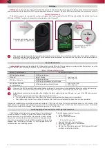
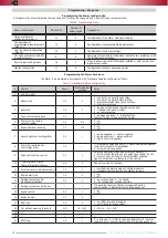
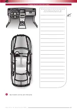
Inputs/outputs of the Alarm are described in the following tables. Contact numbers are shown in Fig. 1. Configuration of inputs/outputs is programmed
(see Programming the Alarm hardware features).
1
2
9
18
1
10
4
8
5
2
4
1
3
Fig. 1. Numbers of port connector pins from wiring viewpoint
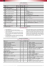
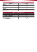
Table 4. Description of the systems main (18-pin) connector
Connector
#
Color
Type
Note
Current, mA
18-pin
1
–
Ground
Power for additional devices (TP-BUS)
–
2
Blue/Yellow
–
Heater WBUS(Webasto, Ebersacher)
–
3
Brown
CAN 2
CAN2-L bus
–
4
Brown
CAN 1
CAN1-L bus
–
5
Pink/Green
(+) programmable input
Stop signal control
1,5
6
White/Black
(-) output
Wired engine lock
150
7
Gray/Black
(-) programmable input
Reference ground/Negative button
0,5
8
Yellow/Red
Data link
Connection between main unit and lock relay
–
9
Black
Ground
Power
–
10
–
+12 V
Power for additional devices (TP-BUS)
–
11
–
–
TP-BUS (control bus for additional devices)
–
12
Brown/Yellow
CAN 2
CAN2-H bus
–
13
Brown/Red
CAN 1
CAN1-H bus
–
14
Green/Black
(-) programmable input
Hood position control
1,5
15
Blue/Red
(+/-) programmable output
Turn signals alternate control
±150
16
Gray/Yellow
(+) programmable input
Analog buttons/Positive button
0,5
17
Pink/Black
(+/-) output
Siren c)/Horn control(-)
1,300/150
18
Red
+12 V
Power supply
1,500/10*
8-pin
1
Orange/Green
(–) Programmable input
Engine shutdown in remote start
1,5
2
Orange/White
(+) Programmable input
Disable alert if trunk is open
1,5
3
Yellow
(+) microphone
Microphone
–
4
Black
(–) microphone
Microphone
–
5
Yellow/White
(–) Programmable output
Front parking sensors control
150
6
Green/White
(–) Programmable output
Rear parking sensors control
150
7
Green
(–) Programmable output
Impulse to close the hood/Alternate Central
Lock control (Lock for twin-wire control. Lock/
Unlock for one-wire central lock control)
150
8
Blue
(–) Programmable output
Authentication pulse/Alternate Central Lock
control (Unlock for twin-wire Central Lock
control)
150
4-pin
1
Red/White
Power supply
+12 V power supply for Fortin or iDatalink
unit
2
Black/Yellow
Power supply
Ground for Fortin or iDatalink unit
3
Gray/Blue
DATA(RX) connect to the
blue wire (Fortin) or black/
white (iDatalink) wire
Control of a Fortin or iDatalink unit
4
Gray/Green
DATA(TX) connect to the
white wire (Fortin) or
black/white (iDatalink)
wire
Control of a Fortin or iDatalink unit
2-pin(LED)
1
Red
(+) output
+12 V power supply
2
Blue
(–) output
Ground
*
Given is the average current value in operating and idle modes. It is subject to change according to positive outputs demand.
Useful current of output
#9
depends on demand connected to negative outputs.
Outputs
#6,
15, and 17 are protected from short-circuit, inductive eruptions, overheating, and overload.
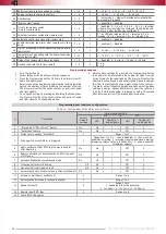
Connector
#
Color
Type
Note
Current, mA
18-pin
1
Black
Ground
For TEC-810/830.
Power for additional devices
For TEC-810/830 with thermal sensor
Ground for engine temperature sensor
–
2
Blue/Yellow
–
Heater WBUS (Webasto, Ebersacher)
–
3
Brown
CAN 2
CAN2-L bus
–
4
Brown
CAN 1
CAN1-L bus
–
5
Pink/Green
(+) programmable input Stop signal control
1,5
6
White/Black
(-) output
Wired engine lock
150
7
Gray/Black
(-) programmable input
Reference ground/Negative button
0,5
8
Yellow/Red
Data link
Connection between main unit and lock relay
–
9
Black
Ground
Power
–
10
For TEC-810/830.
Red
For TEC-810/830
with thermal
sensor
Black/White
+12 V
For TEC-810/830.
Power for additional devices
For TEC-810/830 with thermal sensor
Power for engine temperature sensor
–
11
–
–
TP-BUS (control bus for additional devices)
–
12
Brown/Yellow
CAN 2
CAN2-H bus
–
13
Brown/Red
CAN 1
CAN1-H bus
–
14
Green/Black
(-) programmable input
Hood position control
1,5
15
Blue/Red
(+/-) programmable
output
Turn signals alternate control
±150
16
Gray/Yellow
(+) programmable input Analog buttons/Positive button
0,5
17
Pink/Black
(+/-) output
Siren c)/Horn control(-)
1,300/150
18
Red
+12 V
Power supply
1,500/10*
8-pin
1
Orange/Green
(–) Programmable input Engine shutdown in remote start
1,5
2
Orange/White
(+) Programmable input Disable alert if trunk is open
1,5
3
Yellow
(+) microphone
Microphone
–
4
Black
(–) microphone
Microphone
–
5
Yellow/White
(–) Programmable
output
Front parking sensors control
150
6
Green/White
(–) Programmable
output
Rear parking sensors control
150
7
Green
(–) Programmable
output
Impulse to close the hood/Alternate Central Lock
control (Lock for twin-wire control. Lock/Unlock
for one-wire central lock control)
150
8
Blue
(–) Programmable
output
Authentication pulse/Alternate Central Lock
control (Unlock for twin-wire Central Lock
control)
150
4-pin
1
Red/White
Power supply
+12 V power supply for Fortin or iDatalink unit
2
Black/Yellow
Power supply
Ground for Fortin or iDatalink unit
3
Gray/Blue
DATA(RX) connect
to the blue wire
(Fortin) or black/white
(iDatalink) wire
Control of a Fortin or iDatalink unit
4
Gray/Green
DATA(TX) connect
to the white wire
(Fortin) or black/white
(iDatalink) wire
Control of a Fortin or iDatalink unit
2-pin(LED)
1
Red
(+) output
+12 V power supply
2
Blue
(–) output
Ground
*
Given is the average current value in operating and idle modes. It is subject to change according to positive outputs demand.
Useful current of output
#9
depends on demand connected to negative outputs.
Outputs
#6,
15, and 17 are protected from short-circuit, inductive eruptions, overheating, and overload.


