A6V10323934_c_en_--
SIEMENS Industry, Inc.
2020-01-16
Smart Infrastructure
Installation Instructions
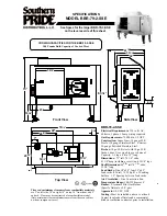
Model FDOT421
Multi-Criteria Smoke Detector
UL268 7th edition listed
Figure 1
These instructions are written in accordance with the
installation guidelines of NFPA 72, National Fire Alarm
Code, and CAN/ULC-S524, The Installation of Fire Alarm
Systems.
Do not locate the detectors next to an oil burner, or
garage where exhaust fumes can trigger an alarm. Other
causes of false alarms are dust accumulation, heavy
concentrations of steam, heavy pipe or cigar smoke, and
certain aerosol sprays.
CAUTION
DO NOT install this detection device until all construction
is completed.
DO NOT store this detection device where it can be
contaminated by dirt, dust, or humidity.
AIR CURRENTS
Before a detector can sense a fire, the products of
combustion or smoke must travel from the fire to the
detector. This travel is especially influenced by air
currents; therefore, consider air movement when
designing the system. While combustion products tend
to rise, drafts from hallways, air diffusers, fans, etc., may
help or hinder the travel of combustion products to the
detector. When positioning a detector at a particular
location, give consideration to windows and doors, both
open and closed, to ventilating systems, both in and out
of operation, and to other factors influencing air
movement. Do not install a detector in the air stream of
a room air supply diffuser. It is better to position a
detector closer to an air return.
The distance that products of combustion or smoke
travel from a fire to the detector is not usually the shortest
linear route. Combustion products or smoke usually rise
to the ceiling, then spread out. Average ceiling heights of
8 to 10 feet do not abnormally affect detector response.
High ceilings, located in churches, warehouses,
auditoriums, etc., do affect detector response and should
be considered.
SPECIAL CEILING CONSTRUCTION FACTORS
Ceiling obstructions change the natural movement of air
and combustion products. Depending on the direction of
smoke travel, joists and beams can slow the movement
of heated air and smoke, while pockets between them
can contain a reduced level of smoke. Take obstructions
created by girders, joists, beams, air conditioning ducts,
or architectural design into consideration when
determining area protection. Refer to the Initiating
Devices chapter of NFPA Standard 72 for Location and
Spacing requirements for specific types of construction;
e.g. beam, suspended, level, sloped and peaked
ceilings. The detector is also compatible with the
following mechanical protection guard model: STI-9604
(see www.STI-USA.com for details).
DETECTOR PLACEMENT
Although no specific spacings are set for the detectors
used for a clean air application, use 30-foot center
spacing (900 sq ft) from NFPA Standard 72 initiating
devices chapter and CAN/ULC-S524, if practical, as a
guide or starting point for a detector installation layout.
This spacing, however, is based on ideal conditions –
smooth ceiling, no air movement, and no physical
obstructions.
In
some
applications,
therefore,
considerably less area is protected adequately by each
smoke detector. This is why it is mandatory to closely
follow the installation drawings. In all installations place
the detector on the ceiling, a minimum of 6 inches from
a side wall, or on a wall, 12 inches from the ceiling.
If the detector is used as heat only
locate it on the
ceiling, at least 4 inches from the side walls. For an
ideal, smooth ceiling condition, place the detectors at a
maximum center spacing of 50 feet (2500 square
feet).
Drawings provided or approved by Siemens
Industry, Inc., or by its authorized distributors are
extremely important
.
The detector placements shown on
these drawings were chosen after a careful evaluation of
the area that is protected. Such factors as air currents,
temperature, humidity, pressure, and the nature of the
fire load were carefully considered. Especially noted
were the room or area configuration and the type of
ceiling (sloped or flat, smooth or beamed). Siemens
Industry, Inc.’s extensive experience in the design of the
system assures the best detector placement by following
these drawings. Sound engineering judgment by
qualified personnel must be followed.
TO AVOID NUISANCE ALARMS
Do not locate the detectors where excessive smoke
concentrations exist under normal conditions, or in areas
of prolonged high relative humidity where condensation
occurs.