background image


10


15

14

16

17

13

12


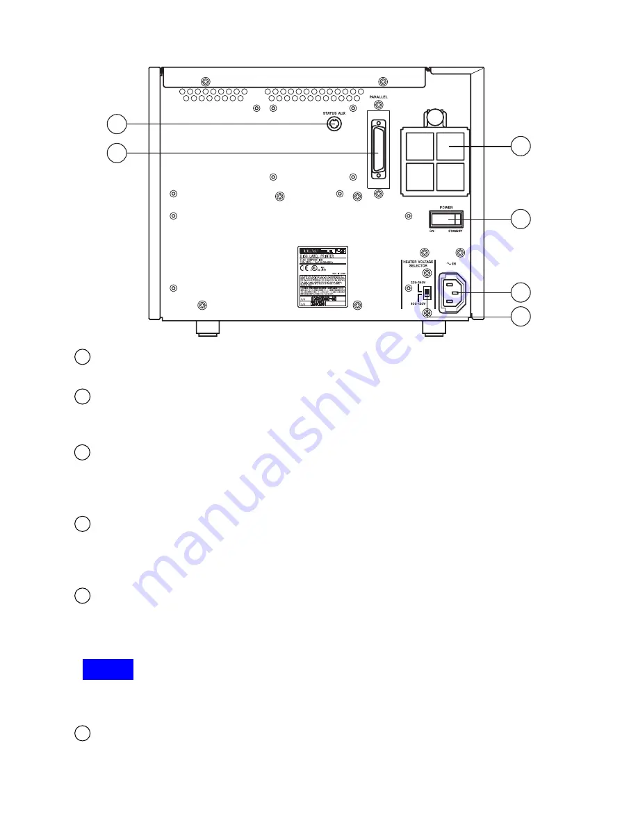
STATUS AUX Connector (optional) 

This connector is not used when using the P-55 alone. 

Parallel Port Multi-connector 

This provides a parallel interface between your PC's printer port and the P-55 over the supplied 
printer cable. 

Intake Fan (with filter) 

This opening is for dropping the temperature inside the unit. Obstructing this opening may result 
in failures. Place the unit in an adequate location. (See Section 4, Choosing an Adequate 
Location.) 

Power Switch 

This rocker switch turns power to the unit on and off. The unit powers up when pressing the ON 
end of the switch, and    powers down when pressing the STANDBY end. (The internal cooling fan 
stops only in about 10-20 minutes after the unit switches into the Standby mode.) 

AC Power Input Socket 

Plug in here the power cable. (To drop the temperature inside the unit, the fan continues to rotate 
for about 10 to 20 minutes after switching off the power. For this interval of time, do not unplug the 
power cable.) 


NOTE 

The product for U.S.A., Canada and Europe does not include a power cable. See Section 8, 
Connections. 

Heater Voltage Selector Switch 

This selects the voltage to supply to the internal heater. As shipped from the factory, this switch is 
set to "100-120V". Change the setting depending on your local line voltage. If this switch is not set 
correctly, failures may result. 

12 

13 

14 

15 

16 

17 

Summary of Contents for P-55KIT

Page 1: ...P 55KIT P 55 DISC LABEL PRINTER INSTRUCTION MANUAL REV C...

Page 2: ...venience receptacles and the point where they exit from the apparatus 11 Only use attachments accessories specified by the manufacturer 12 Use only with the cart stand tripod bracket or table specifie...

Page 3: ...3 IMPORTANT SAFETY INSTRUCTIONS...

Page 4: ...lel Interface Mode on the PC 14 Section 7 Installing the Label Editor 15 Section 8 Connections 17 Section 9 Installing the Printer Driver 19 Section 10 Control Panel Features 20 Section 11 Error Messa...

Page 5: ...apabilities P 55 Features Thermal re transfer printer capable of generating photo quality full color output at 24 bits and 256 gradation levels per color Variable dot technology implemented enabling t...

Page 6: ...ble bar code capable E Fade Out with Time UV resistant overcoating G UV resistant ink and overcoating E Durability Scratch resistant overcoating E Scratch resistant overcoating E Media Accommodation S...

Page 7: ...missing or damaged contact your dealer Accessories for P 55 and P 55KIT Accessories for P 55KIT ONLY Utility Software CD ROM x1 including Operation Manual Printer Driver and Disc Label Editor Photo ri...

Page 8: ...te location Side Door Unlocking Button Pressing this button opens the side door The side door is locked when the unit is turned on for how to unlock the lock when the unit is turned on see Section 12...

Page 9: ...ot contain re transfer ribbon Lock Lever This is for locking the ribbon cartridge in place Tray Door The tray slides out Do not place any objects in front of this door Tray Tray Adapter Lock Switch Tr...

Page 10: ...the switch and powers down when pressing the STANDBY end The internal cooling fan stops only in about 10 20 minutes after the unit switches into the Standby mode AC Power Input Socket Plug in here the...

Page 11: ...print head and heat roller So you should be concerned with air circulation CAUTION Do not block the lateral exhaust opening and the rear intake opening by walls or other obstacles a free space of mor...

Page 12: ...power is turned on or just after turning off the power WARNING Do not put your fingers or sleeves close to the tray sliding in or out They can be got in possibly causing injuries CAUTION Never switch...

Page 13: ...lace Store the bar for future use by attaching it to where marked 3 Peel off adhesive tape flip up lock lever to unlock the ribbon cartridge and remove two cushions by pulling them toward you IMPORTAN...

Page 14: ...ction 6 Setting the Parallel Interface Mode on the PC To use the P 55 you need to set your PC s parallel port to ECP mode This setting is made in the BIOS setup For how to do this refer to your PC s m...

Page 15: ...rive and an installation wizard will automatically start If the installation wizard does not start automatically click Start Menu My Computer CD ROM SETUP Choose Setup Language window comes up Select...

Page 16: ...hield Wizard Complete window comes up Click Finish Disc Label Editor Setup Complete comes up Place a check beside Yes I want to restart my computer now and click Finish The P 55 is now ready to be use...

Page 17: ...ains plug conforming to CEE7 a connector conforming to EN60320 1 and a mains cable conforming to CEE13 The connector must be rated at more than 10A and 250V As shipped from the factory the heater volt...

Page 18: ...front control panel will change as follows I n i t i a l R A M T E A C P 5 5 R e v X X X X I n i t i a l W a r m i n g u p It takes a few minutes for the warming up process to complete R e a d y o r...

Page 19: ...zard window comes up Place a check beside Install the software automatically Recommended and click Next Please select the best match for window comes up Choose TEAC P 55 Disc Label Printer and click N...

Page 20: ...ion Error Messages Explained LOAD EJECT button lets the tray slide out and in This button is not available in the process of printing that is when Busy is shown on the LCD SELECT button rotates the fu...

Page 21: ...s will start For how to set up a medium on the tray refer to Section 13 Loading Print Media When the disc tray slides out and you press the ENTER button the tray slides in and the P 55 switches back i...

Page 22: ...k B U S Y P r i n t i n g Y e l l o w B U S Y P r i n t i n g M a g e n t a B U S Y P r i n t i n g C y a n The LCD shows the following when dyes are being transferred from the re transfer ribbon to t...

Page 23: ...ed or no re transfer ribbon is loaded see Notes 1 2 and 3 Change the re transfer ribbon by referring to Section 12 or load a usable re transfer ribbon ERROR TFR Ribbon Jam The re transfer ribbon is st...

Page 24: ...sfer ribbon rewound by the length of more than one disc Figure 1 ERROR TFR Ribbon End is displayed even not at the end of the ribbon If this is the case perform the following refer to Section 12 when...

Page 25: ...w to mount the disc adapter 1 Set the slide switch on the front of the tray drawer to the RELEASE position 2 Snap the protrusion of the adapter into the cut out in the tray as shown below 3 Make sure...

Page 26: ...igh temperature and high humidity environment or place subject to direct sunlight allowable temperature 5 30 C humidity 10 80 Prevent condensation from forming on ribbons while they are stored For hig...

Page 27: ...on on the top left of the unit and slowly open the hinged door down 2 Loading Ink Ribbon 1 Flip up the lock lever that holds the ink ribbon cartridge in place 2 Take out the ink ribbon cartridge by pu...

Page 28: ...ft into the hole provided in the cartridge for ease of work we recommend holding the shaft by inserting your index finger into its open end and snap the protrusion at the other end of the shaft into t...

Page 29: ...ntwise there is a chance that the ribbon might be broken If the ribbon clogs somewhere take out the cartridge take up ribbon slack again and slowly re insert the cartridge 3 Loading Re transfer Ribbon...

Page 30: ...shaft into the hole provided in the cartridge for ease of work we recommend holding the shaft by inserting your index finger into its open end and snap the protrusion at the other end of the shaft in...

Page 31: ...e unless you lock the ribbon cartridges in place with the lock lever If you try to forcibly close the side door there is a chance that the side door might be damaged Caution in ribbon replacement It i...

Page 32: ...s necessary for Ink Remain to appear on the LCD and then press the ENTER button 3 T R F 9 9 I N K 9 9 The re transfer ribbon s remaining amount is indicated on the upper line and the ink ribbon s rema...

Page 33: ...let the tray slide in 4 When the tray has fully slid in the READY lamp will light up Then let the printing process start through graphics software in use NOTES Do not place any objects other than the...

Page 34: ...Label Printer shown in the label editor NAME box and click Properties 4 Perform the following for the best possible output quality 4 1 In the Color field select a Method suited to the image you use 4...

Page 35: ...is completed the tray slides out To print on multiple media take out the medium from the tray load another medium and click OK 2 Correcting for displacement and hue shift between colors With the P 55...

Page 36: ...36 2 Select TEAC P 55 Disc Label Printer and click Set printer properties 3 Click Printing Preferences 4 Click the Maintenance tab...

Page 37: ...6 The first test pattern print process will start 7 When the first test pattern has been printed take out the medium from the disc tray and rotate the medium by 180 degrees and place it on the tray s...

Page 38: ...and the left and right scales relate to horizontal adjustment 10 A pair of longer and shorter lines are printed along the vertical and horizontal scales Determine which pair of longer and shorter lin...

Page 39: ...medium from the tray and determine which pair of black and colored lines are aligned or which pair of lines have the slightest displacement between per Cyan Magenta and Yellow and enter the corrective...

Page 40: ...ick Print next to Aspect ratio on the Maintenance dialog 2 The first test pattern is printed 3 Take out the medium rotate it by 90 degrees and place the medium again on the tray so that the arrow mark...

Page 41: ...s least displaced with respect to a scale mark You can use either the upper and lower scales or the left and right scales In the above example you can get a value of 2 on the upper scale and a value o...

Page 42: ...ain and this causes its uniformity in resistivity to lose and thus producing a residual image This is due to the inherent characteristics of the print heads available and inevitable To lessen the resi...

Page 43: ...and press the ENTER button 2 Open the side door by pressing the button on the top left of the printer 3 Release the lock on the ribbon cartridge by flipping up the lock lever 4 Pull out the ribbon ca...

Page 44: ...to stop and unplug the power cord To drop the temperature inside the unit the fan continues to rotate for about 10 to 20 minutes after switching off the power WARNING Areas indicated by the hazardous...

Page 45: ...ls in reverse order of removal by referring to Section 5 Removing Shipping Materials Thereafter pack the printer by referring to the illustration below NOTE Shipping the P 55 without shipping material...

Page 46: ...color black ink ribbon 1000 discs ribbon Re transfer color ribbon 500 discs ribbon Compatible Media TEAC specified thermal printable discs Printable Image Size 12 cm CD 2048 pixels by 2048 pixels Ima...

Page 47: ...47 3 External Dimensions...

Page 48: ...20 Purpose designed cartridge additionally required Color Re transfer Ribbon Set Part No 19610050 30 including 2 re transfer ribbons Ribbon Cartridge Single Color Ink Ribbon Cartridge Part No 1961006...

Page 49: ...ent Bahnstrasse 12 D 65205 Wiesbaden Erbenheim Germany Phone 49 611 7158 675 Fax 49 611 7158 666 e mail info teac roboflex de sales teac roboflex de URL www teac roboflex de Technical Support TEAC Ame...

Reviews: