114-94163-2
Rev C
15 of 20
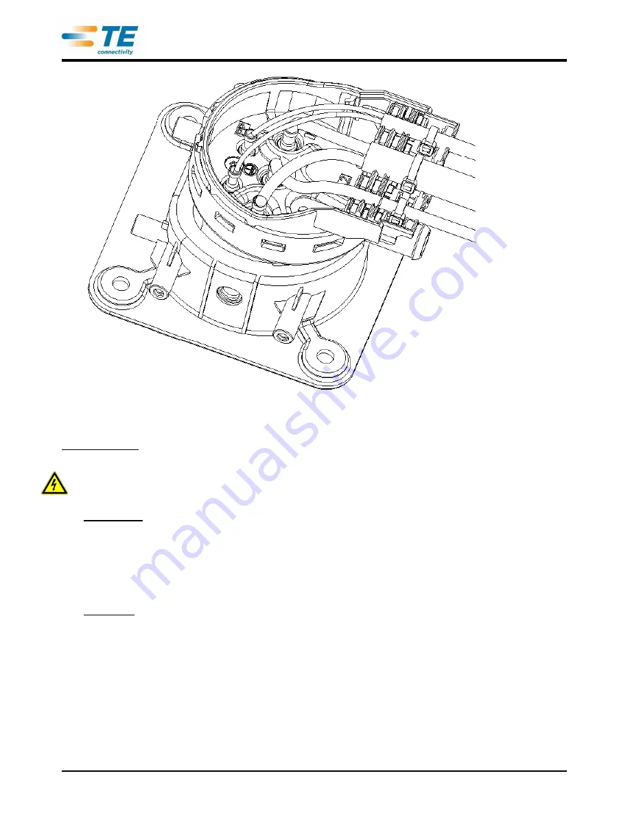
Figure /
Bild
10
Step 9
/ Schritt 9
After the contacts have been controlled for correct positioning and locking, the Secondary Lock
has to be pressed in from the frontside (figure 11). The adequate locking must be ensured and
checked (dimensional check of correct position (figure 11). The secondary lock has to be secured
with the screw from the backside (screwing torque 0,9 +/- 0,15 Nm) (figure 12).
ATTENTION: The correct pinning has to be ensured BEFORE locking the Secondary Lock!
Rewiring is not possible after locking the Secondary Lock without destroying the plastic parts.
Nachdem die Kammern bestückt und die Kontakte auf vorschriftsmäßigen Sitz geprüft wurden, muss die
Zweite Kontaktsicherung von vorne in das Ladedosengehäuse eingerastet werden (Bild 11). Das
ordnungsgemäße Verrasten muss sichergestellt und geprüft werden (Einpresstiefe in das Gehäuse, Bild
11). Die Zweite Kontaktsicherung ist mit der Schraube von der Rückseite zu sichern
(
Anzugsdrehmoment 0,9 +/- 0,15 Nm
)(Bild 12).
ACHTUNG: Die korrekte Kontaktbelegung ist VOR der Verrastung der Zweiten Kontaktsicherung sicher zu
stellen! Eine Änderung der Kontaktbelegung ist nach Verrastung der Zweiten Kontaktsicherung nicht mehr
ohne Zerstörung der Kunststoffteile möglich.


