114-94163-2
Rev C
13 of 20
Step 7
/ Schritt 7
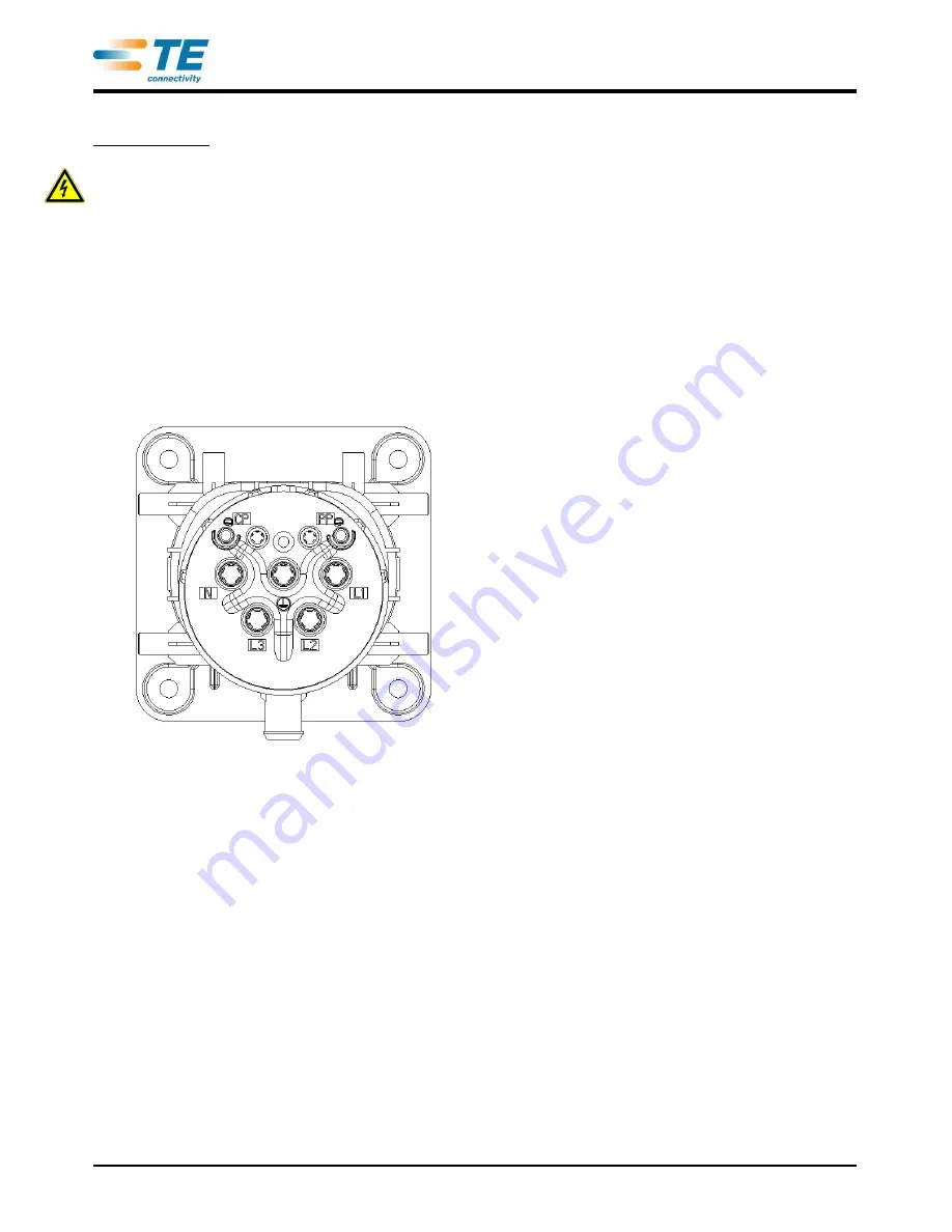
Insert the Contacts from the backside into the Charge Inlet Housing according to the cavity
description (figure 8) into their locking position. To ensure that the contacts are correctly inserted,
pull and push with a low force on the cables (max. 10N) and check visually on the front side that
the locking lances are properly engaged in the related pin groove. The locking lances must not
stay outside of the grooves (figure 9). Ensure the O-Rings are properly positioned in their seats
and are not damaged!
Die Kontakte von der Rückseite entsprechend der Kammerbeschriftung (Bild 8) in das Kontaktgehäuse bis
zur Einrastposition einschieben. Zum Prüfen der Verrastung an der Leitung in und entgegen der
Steckrichtung ziehen bzw. drücken (max. 10N) und dabei die korrekte Verrastung der Rastlanzen in der
Rille der Stifte von der Vorderseite kontrollieren. Die Rastlanzen dürfen nicht außerhalb der Rillen stehen
(Bild 9). Dabei sicherstellen, dass die O-Ringe korrekt in ihren Sitzen positioniert sind und nicht beschädigt
wurden!
Figure /
Bild
8


