408-32027
4 of 11
Rev A
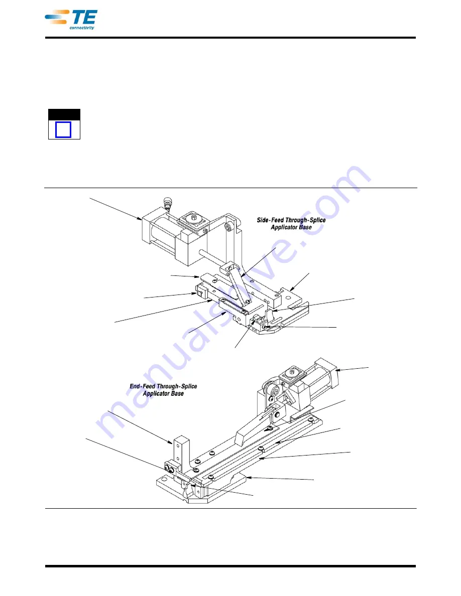
Terminal strip is fed into the applicator with the barrel
(wire) end first, between the front (outer) and rear
(inner) strip guides. It passes the stock drag, and the
LEAD terminal is positioned over the anvil. The feed
pawl feeds one terminal during each cycle of the
machine. The terminals are fed by the action of the air
cylinder that is controlled by a valve on the terminator.
NOTE
i
Some applicators have a solid metal hold-down
that may require adjustment when changing the
wire size and/or crimp height.
Terminals with dual-carrier strips require a shear
depressor, spacer, and terminal holder. These parts
are also attached to the tool holder assembly. The rear
shear depressor pushes the rear floating shear down
to cut the terminal from the rear carrier strip, and the
terminal holder keeps the terminal from raising during
the crimping and shearing process.
The anvil, the front shear holder, the rear shear holder
(if used), the terminal support, and the strip guide
adjustment block are mounted on the base plate, as
well as the rear floating shear and rear shear holder.
The strip guide plate (Figure 5) is fastened to the strip
guide adjustment block. The stock drag, the strip
guide cover plate, and the front and rear strip guides
are mounted on the strip guide plate.
The applicators used for the through-splice application
are PRE-FEED Applicators. This means that the lead
terminal is over the anvil when the machine is at rest.
Feed Cylinder
Front Strip Guide
Strip Guide Plate
Strip Guide
Adjusting Block
Terminal Drag
Shear Retaining Screw
Anvil
Applicator
Base Plate
Feed Finger
Feed Bracket
Stripper
Anvil
Applicator
Base Plate
Strip Guide Plate
Front Strip Guide
Rear Strip Guide
Floating Shear
Feed Finger
Feed Cylinder
Figure 5


