background image

TDI-Dynaload Division 

WCL488 Series Water Cooled Electronic Loads 

Operation & Programming Manual 


402828, Rev. B1 

Page 17 


the water shutoff relay. 

The WCL488 Terminal Block and Terminal Block 

Connections 

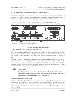
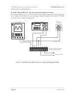
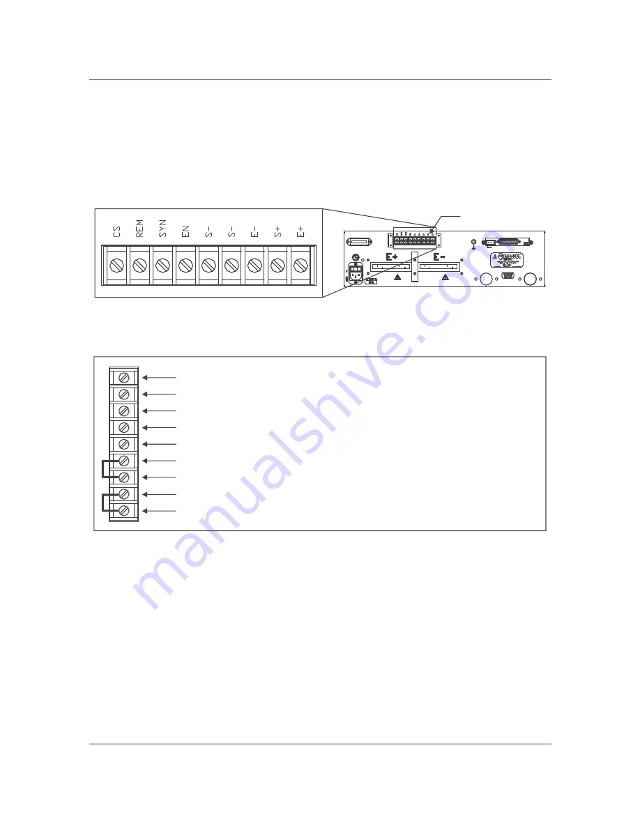
Refer to Figure 14 through Figure 16, and the sections that follow to better understand the wiring 

connections that can be made to the terminal block. 
 

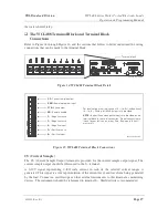
Figure 14. WCL488 Terminal Block Detail 


Figure 15. WCL488 Terminal Block Connections 

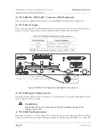
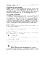
CS (Current Sample) 

The CS (Current Sample Output) terminal is provided for the current sample output signal. The 

current sample output should be referenced to the S– terminal. 
A  0-10V  signal  representing  0-full  scale  current  in  each  of  the  selected  current  ranges  is 

generated. This signal is a true representation of the current level and waveform being generated 

by the load. Connect an oscilloscope or other external instruments to this terminal as monitoring 

devices. The instruments should be referenced to terminal S–. Shielded wire is recommended. 

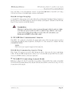
For local voltage sensing, connect (S+) to (E+) and connect 

(S-) to (E-). Factory installed jum pers are provided.

 the positive and negative inputs are provided on the 

term inal block for ease of connection. D o not connect these 

inputs to your test source at any tim e. D am age to the unit 

m ay result.

NOTE:

402825-02-09.C D R

CS:

 C urrent sam ple output

REM: 

R em ote program  input

SYN: 

Sync output

EN: 

R em ote enable

S–: 

N egative sense

S–: 

N egative sense

E–: 

N egative input

S+: 

Positive sense

E+: 

Positive input

402828-02-10.C D R

Term inal block

AC

SELECT

25

0V

F3

.1

5A

HIGH

CURRENT

IEEE

IEEE

T IGHT EN

SECURELY

FLUID 

INLET

RELAY

SLAVE

COMMUNICA TION

FL

GND

FLUID 

OUTLET

OFF/ ON

UV

Summary of Contents for TDI-Dynaload WCL488 Series

Page 1: ...WCL488 Series Water Cooled Electronic Loads Operation Programming Manual TDI Dynaload Division Document Number 402828 Revision B1...

Page 2: ...led and used in accordance with the instruction manual may cause interference to radio communications Operation of this equipment in a residential area may cause harmful interference in which case the...

Page 3: ...and Requirements 8 Thermal Transfer Characteristics 8 Special Information for Ethylene Glycol Users 11 WCL488 Typical Rear Panel Connections 12 WCL488 Rear Panel Electrical Connections 13 WCL488 E an...

Page 4: ...ating Mode Guidelines 22 CI Constant Current Mode Basic Mode 22 CR Constant Resistance Mode Basic Mode 22 CV Constant Voltage Mode Basic Mode 23 CP Constant Power Mode Basic Mode 23 Short Circuit 23 M...

Page 5: ...uctance On Pulse Loading 31 Effects Of Cable Length 32 Current Oscillation 32 Line Loss 32 Transconductance 34 Location Airflow Maintenance 34 WCL488 WCS Water Cooled Load Systems 35 Synchronized Para...

Page 6: ...ata Separators 46 Program Line Terminators 46 Numerical Data Formats 46 Numerical Data Units 46 Power on Defaults 48 Commands 49 Queries 49 Command and Queries Listed Alphabetically 50 Commands and Qu...

Page 7: ...64 FQ Frequency 65 I Read Current 65 I1 Constant Current Pulsing Base Level 66 I2 Constant Current Pulsing Peak Level 66 ID Identification 66 IL Current Limit 67 LAT Latch register 68 LOAD Load On Off...

Page 8: ...Mode 83 UV Under Voltage 84 V Read Voltage 84 V1 Constant Voltage Pulsing Base Level 85 V2 Constant Voltage Pulsing Peak Level 86 VER Version 86 VL Voltage Limit 86 WF Waveform 87 XM External Modulat...

Page 9: ...ections 12 Figure 10 WCL488 Rear Panel Detail 13 Figure 11 WCL488 AC Input Fuse and Input Voltage Selector 14 Figure 12 WCL488 UV Switch Detail 16 Figure 13 WCL488 Relay Connector and Chassis Ground C...

Page 10: ...ble E WCL488 AC Input Power Requirements 14 Table F Major and Minor Fault Indicators 24 Table G Menu Commands 26 Table H Wire Gauge Ampere Rating Reference Table 33 Table I Input Power Requirements 41...

Page 11: ...simple upgrade in the field Individual units electrical inputs and water inlet and output connections are located on the rear of each unit Single connections are provided for systems unless otherwise...

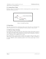
Page 12: ...servo systems batteries and similar DC sources The WCL488 series provides four basic modes of operation Constant Current Constant Resistance Constant Voltage Constant Power and Pulse Mode Complete con...

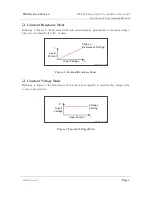
Page 13: ...tional to the input voltage This is set in Amps Volt 1 R or ohms Figure 2 Constant Resistance Mode Constant Voltage Mode Referring to Figure 3 the Dynaload will sink the current required to maintain t...

Page 14: ...itching The WCL488 series provides selection of one of three full scale input voltage ranges and one of three full scale input current ranges The full scale voltage and current ranges may be selected...

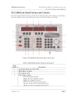
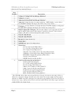
Page 15: ...numbers in the table Figure 5 WCL488 Front Panel Features and Controls Table A WCL488 Front Panel Features and Controls Item Number Description 1 AC Power Power On Power Off 2 IEEE 488 Local Select 3...

Page 16: ...Preset up to 10 configurations 16 Mode Select CI Constant Current Mode Select CV Constant Voltage Mode Select CP Constant Power Mode Select CR LOW Constant Resistance Low Ohm Mode Select CR HIGH Const...

Page 17: ...heir definitions Safety symbols are placed to ensure the safety of Dynaload operators and should never be covered or removed from the equipment WARNING Ensure that all AC and DC power for both the loa...

Page 18: ...unsure about your requirements please consult the factory Each master load assembly or slave assembly has one inlet and one outlet water connection They are 1 2 inch NPT female thread A multitude of a...

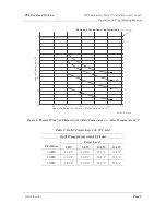
Page 19: ...let Temperature with 10 C Inlet Outlet Temperature with 10 C Inlet Power Level Flow Rate 5 kW 8 kW 10 kW 12 kW 3 GPM 22 1 C 29 8 C 35 6 C 37 4 C 4 GPM 20 3 C 26 2 C 30 1 C 32 3 C 5 GPM 18 3 C 22 8 C 2...

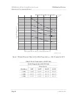
Page 20: ...let Temperature with 20 C Inlet Outlet Temperature with 20 C Inlet Power Level Flow Rate 5 kW 8 kW 10 kW 12 kW 3 GPM 30 8 C 38 2 C 42 5 C 47 8 C 4 GPM 28 7 C 34 5 C 38 2 C 42 8 C 5 GPM 27 2 C 31 8 C 3...

Page 21: ...ls Working within the design limitations of 120 PSI it may not be practical to raise the input pressure of the system in order to achieve the required flow rate It is best to use pure water with no ad...

Page 22: ...Figure 9 Terminal Block Cover shown installed in Rear View Figure 9 WCL488 Typical Rear Panel Connections Relay control cable 402828 02 03 CDR Computer Digital voltmeter IEEE cable Test source AC inp...

Page 23: ...g holes and related hardware found on each of the two input buses located on the left side of the rear of the unit The input buses are separated by an insulator for safety and require lugs with a 7 16...

Page 24: ...The operational frequency range is 47Hz 63Hz Figure 11 WCL488 AC Input Fuse and Input Voltage Selector WCL488 Input Voltage Selector The Input Voltage Selector refer to Figure 11 is mounted on the rea...

Page 25: ...Connect the AC cord first to your Dynaload and THEN to the utility outlet WCL488 Slave Communication Connector This DB25 D connector is located in the upper right corner of the rear panel and is used...

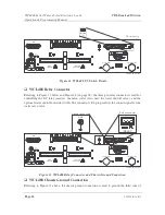
Page 26: ...FL pin provides the control signal for the water servo valve Figure 13 WCL488 Relay Connector and Chassis Ground Connection WCL488 Chassis Ground Connection Referring to Figure 13 above the chassis g...

Page 27: ...is signal is a true representation of the current level and waveform being generated by the load Connect an oscilloscope or other external instruments to this terminal as monitoring devices The instru...

Page 28: ...thout damage to the load When not in pulse mode this output remains high until a current change is executed At this time the output is pulsed low for scope triggering EN Remote Enable The EN Remote En...

Page 29: ...oltage sense wires are connected to the power source terminals This will eliminate potential errors due to voltage drop in the cable It is also recommended to use shielded wire for remote voltage sens...

Page 30: ...ude various optional equipment to the Dynaload In the example shown in Figure 16 an oscilloscope function generator and remote DC ON OFF switch are shown installed to the Dynaload Figure 16 WCL488 Ter...

Page 31: ...ore applying AC or DC voltages to the load 6 Turn on AC power meters should come on and fan should run 7 Step through the Menu settings to be sure the set points are appropriate to the application Che...

Page 32: ...d never be used to test a constant current source The regulation of the two units will fight for control of the current and an unstable oscillation will result CR Constant Resistance Mode Basic Mode T...

Page 33: ...urrent level inversely in response to a change in voltage The constant power mode is NOT affected by changes of the voltage or current range CAUTION If the source voltage decays to zero volts the load...

Page 34: ...the controlling computer By pressing the LOCAL button a second time the unit will return to IEEE control This key will not function if password lockout is enabled See section on password protection P...

Page 35: ...ngage and the SYS fault LED will extinguish when the input voltage goes over 0 4 volts but the UV fault indication remains until cleared with the LOAD ON command over the IEEE bus or by depressing the...

Page 36: ...in appearance The subsections in this section detail each of the menu commands Referring to Table G the menu features are as follows Table G Menu Commands Number Menu Command 1 Current Limit Setting...

Page 37: ...larm condition will be indicated and will be a MAJOR FAULT The load will not reconnect until the input voltage is below the limit set point When prompted press ENTER to select the function then enter...

Page 38: ...488 primary address must be set through the front panel numeric keypad When prompted press ENTER to select this function enter the numeric address you wish the load to respond to and press ENTER Pass...

Page 39: ...load automatically stop loading when the input Voltage drops below a specified threshold If the input Voltage level drops below the UV setting the load will disconnect from the source A UV and MAJOR...

Page 40: ...ommended to monitor the current sample output with an oscilloscope to observe the actual current amplitude and waveform If waveforms other than square waves are required this can be accomplished by pr...

Page 41: ...icrohenry The inductive drop cannot exceed the difference between the source voltage and the minimum compliance EXAMPLE Referring to Equation 1 that follows to test a 10V source with a 100A pulse and...

Page 42: ...If this situation occurs refer to the Effects of Cable Inductance On Pulse Loading section earlier in this chapter Line Loss If the Dynaload is not configured for remote voltage sensing the voltage di...

Page 43: ...4 1 0 1 6 0 81 22 9 5 1 6 2 5 1 28 20 11 7 5 2 5 4 0 3 2 04 18 16 10 6 4 0 6 0 5 3 24 16 22 13 10 6 0 10 0 7 5 16 14 32 17 20 10 0 16 0 15 8 22 12 41 23 30 16 0 26 0 20 13 05 10 55 33 35 25 20 8 8 73...

Page 44: ...l while operating at current levels greater than 10 of the full current rating of the load If the baseline current is greater than 10 of full scale current and the pulsed waveform is added above this...

Page 45: ...on the master to operate Therefore do not attempt to operate the slave units without a master control unit The WCS System is designed to automatically detect the presence of the slave units In operati...

Page 46: ...o two slaves are set to the same number Having two slaves set to the same number will confuse the master and it will not identify the second slave unit Figure 17 Slave Bit Identifier Switches The mast...

Page 47: ...Wiring The main components of Water Cooled Load Systems are as follows Main servo unit DC relay master Relay master load Relay slave load Water shutoff valve master Water shutoff valve one per slave O...

Page 48: ...tems Wiring Diagram FL 402828 02 04 CDR Main servo unit Optional water shutoff override switch mom entary Water shutoff valve one per slave Water shutoff valve master Relay slave load Relay master loa...

Page 49: ...Switch The switch powers the WCS unit ON and OFF Status Indicators AC ON indicates that the WCS unit is powered on DC ON indicates that the WCL488 is powered on and sending control information for us...

Page 50: ...h a 7 16 inch diameter hole CAUTION Only the power source to load connections are to be made to these buses Always be sure these connections are securely tightened A loose connection will result in a...

Page 51: ...ctor The Input Voltage Selector refer to Figure 21 is mounted on the rear panel immediately above the AC input and fuse assembly NOTE Each WCS slave Input Voltage Selector MUST be set the same as the...

Page 52: ...or equivalent OR GDC 3 15A 250V 3 15 Amp 250 Volt slow blow 20 mm European version or equivalent WCS Slave Communication Connector This DB25 D connector is located in the upper right corner of the rea...

Page 53: ...tor see Figure 13 and Figure 18 on page 38 this connector does not have an FL pin which on a WCL488 or master unit controls the water servo Figure 23 WCS Relay Connector and Chassis Ground Connection...

Page 54: ...st be placed the OFF position IMPORTANT You must be sure that no two slaves are set to the same number Having two slaves set to the same number will confuse the master The master will not identify the...

Page 55: ...the IEEE 488 bus subset capabilities indicated in Table J Table J Bus Subset Capabilities Subset Category Response Acceptor Handshake AH1 Full capability the load can generate the handshake for recei...

Page 56: ...or as a carriage return only by following the IEEE 488 bus configuration procedure Numerical Data Formats The programmable Dynaload accepts the two numerical data formats listed below see Table K Thes...

Page 57: ...gh ohms Ohms CRL Constant resistance setpoint Low ohms Ohms CV Constant voltage setpoint Volts Volts DU Square wave duty cycle Percent FQ Square wave frequency Hertz Hz I Load current Amperes Amps I1...

Page 58: ...nstant resistance setpoint CV Constant voltage setpoint Vmax DU Square wave duty cycle 50 FQ Square wave frequency 1000 Hz I1 First current value 0 I2 Second current value 0 IL Current limit 105 of fu...

Page 59: ...ands followed by a question mark are queries When received by the Dynaload the appropriate information is stored for reading by the IEEE 488 bus controller It is important to note that the results of...

Page 60: ...ant Power setting CR Read Constant Resistance setting CRH NR2 Set Constant Resistance High mode CRL NR2 Set Constant Resistance Low mode CV NR2 Set Constant Voltage mode CV Read Constant Voltage setti...

Page 61: ...ant Resistance pulse base level R1 Read Constant Resistance pulse base setting R2 NR2 Set Constant Resistance pulse peak level R2 Read Constant Resistance pulse peak setting RNG NR1 Set Voltage Curren...

Page 62: ...oltage V1 NR2 Set Constant Voltage pulse base level V1 Read Constant Voltage pulse base level V2 NR2 Set Constant Voltage pulse peak level V2 Read Constant Voltage pulse peak level VER Read software v...

Page 63: ...d Shutdown register TEXT OFF Set numeric query responses TEXT ON Set descriptive query responses TEXT Read Text on off setting Identification ID Read Identification string VER Read software version st...

Page 64: ...gh mode CRL NR2 Set Constant Resistance Low mode CV NR2 Set Constant Voltage mode CV Read Constant Voltage setting MODE Read mode XM ON Set External Modulation on XM OFF Set External Modulation off XM...

Page 65: ...P1 NR2 Set Constant Power pulse base level P1 Read Constant Power pulse base setting P2 NR2 Set Constant Power pulse peak level P2 Read Constant Power pulse peak setting R1 NR2 Set Constant Resistanc...

Page 66: ...register ERR Read Error Register LAT NR2 Set the fault Latch register LAT Read the Latch register setting SBE NR1 Set Summary Bit Enable register SBE Read Summary Bit Enable register SDN NR1 Set Shutd...

Page 67: ...YNTAX Shows the proper form s of the command Spaces are optional as the command processor ignores these EXAMPLE Gives an example of command usage QUERY SYNTAX Provides the proper query form RETURNED P...

Page 68: ...This will set the peak level to 50 Amps per Volt above the base level Therefore if the base level setting is 25A the peaks will be 75 Amps per Volt Query Syntax AV2 Returned Parameters TEXT ON NR2 am...

Page 69: ...2 5 This will place the load in Amps Volt Low mode at 2 5 Amps per Volt Query Syntax AV Returned Parameters TEXT ON NR2 amps v TEXT OFF NR2 CI Constant Current Set Constant Current mode and current v...

Page 70: ...ective bit in the Shutdown SDN register is set the load will shutdown The returned value will be between 0 and 255 and is the sum of the individual bit weights The individual bits are defined below Bi...

Page 71: ...place the load in Constant Power at 20 Amps Query Syntax CP Returned Parameters TEXT ON NR2 watts TEXT OFF NR2 CR See query form of CRH and CRL that immediately follow CRH Constant Resistance High Des...

Page 72: ...mand Syntax CRL NR2 Example CRL 1 5 This will place the load in Constant Resistance Low mode at 1 5 Ohms Query Syntax CR Returned Parameters TEXT ON NR2 ohms TEXT OFF NR2 CV Constant Voltage Descripti...

Page 73: ...ng This defines the percentage of peak pulse time and will set the Pulsing Base Time T1 and Pulsing Peak Time T2 accordingly based upon the defined frequency Command Syntax DU NR2 Example DU 40 0 This...

Page 74: ...individual bit weights as defined below Bit Weight Description Text On Response Message 7 128 6 64 5 32 Command not allowed NOT ALLOWED 4 16 Command too long TOO LONG 3 8 Numeric Error NUMERIC 2 4 1 2...

Page 75: ...djusted accordingly based upon the defined duty cycle Command Syntax FQ NR2 Example FQ 1000 0 This will set the frequency to 1000Hz If the duty cycle was 30 T2 will be set to 300 s and T1 will be set...

Page 76: ...l Description This command is used to set the peak level relative to the base level when pulse loading in the Constant Current mode Command Syntax I2 NR2 Example I2 25 0 This will set the peak level t...

Page 77: ...67 IL Current Limit Description This command is used to set the Current Limit set point The Current Limit circuit will not allow the load current to exceed this level Command Syntax IL NR2 Example IL...

Page 78: ...cription Text On Response Message Default Value 7 128 Under Voltage UV 0 6 64 Over Voltage OV 0 5 32 Over Temperature OT 0 4 16 0 3 8 Over Current OC 0 2 4 Over Power OP 0 1 2 Saturation SAT 0 0 1 Mod...

Page 79: ...art loading the device under test at the programmed settings LOAD OFF This will open the load connect relay and stop loading Query Syntax LOAD Returned Parameters TEXT ON TEXT OFF LOAD ON LOAD OFF 1 m...

Page 80: ...des Bit Weight Description Text On Response Message 6 64 Slave Mode SLAVE 5 32 Constant Amps Volt High CONSTANT AMPS VOLT HIGH 4 16 Constant Amps Volt Low CONSTANT AMPS VOLT LOW 3 8 Constant Resistanc...

Page 81: ...Syntax NONE Returned Parameters N A MS Memory Save Description This command saves the load s setup into the specified memory location The memory location number must be a value from 1 through 9 Comman...

Page 82: ...on This command is used to set the peak level relative to the base level when pulse loading in the Constant Power mode Command Syntax P2 NR2 Example P2 20 0 This will set the peak level to 20 Watts ab...

Page 83: ...Returned Parameters TEXT ON NR2 ohms TEXT OFF NR2 R2 Constant Resistance Pulsing Peak Level Description This command is used to set the peak level relative to the base level when pulse loading in the...

Page 84: ...High 2 Medium High 3 Low High 4 High Medium 5 Medium Medium 6 Low Medium 7 High Low 8 Medium Low 9 Low Low Description The Query form of this command returns actual operating range The text response...

Page 85: ...n Programming Manual 402828 Rev B1 Page 75 RST Reset Description This command resets the load to its factory default power on settings Command Syntax RST Example RST This will reset the load to its fa...

Page 86: ...se Message Default Value 7 128 Under Voltage UV 1 6 64 Over Voltage OV 1 5 32 Over Temperature OT 1 4 16 0 3 8 Over Current OC 1 2 4 Over Power OP 1 1 2 Saturation SAT 1 0 1 Module Fault MOD FLT 1 Des...

Page 87: ...e UV 0 6 64 Over Voltage OV 1 5 32 Over Temperature OT 1 4 16 0 3 8 Over Current OC 0 2 4 Over Power OP 0 1 2 Saturation SAT 0 0 1 Module Fault MOD FLT 0 Description The query form of this command wil...

Page 88: ...E Maximum slew rate is highly dependent on factors including power source source to load wiring and operating mode Command Syntax SF Example SF Sets the slew rate limiter to the fast range Query Synta...

Page 89: ...le Shot Complete SINGLE SHOT COMPLETE 4 16 Command Error COMMAND ERROR 3 8 Minor Fault MINOR FAULT 2 4 Major Fault MAJOR FAULT 1 2 System Minor Fault SYSTEM MINOR 0 1 System Major Fault SYSTEM MAJOR D...

Page 90: ...miter to the slow range In the slow range full scale rise and fall times can be programmed between 1 000 s and 400 000 s using the SR S1 or S2 commands NOTE Maximum slew rate is highly dependent on fa...

Page 91: ...it Weight Description Text On Response Message 7 128 Reserved RESERVED 6 64 Change In Status STA CHANGE 5 32 Single Shot Complete SINGLE SHOT COMPLETE 4 16 Command Error COMMAND ERROR 3 8 Minor Fault...

Page 92: ...d Syntax SW NR1 SW OFF Example SW This will turn on Square Wave pulsing until explicitly turned off SW 50 This will turn on Square Wave pulsing for 50 pulses and then return to the base drive level SW...

Page 93: ...T2 NR1 Example T2 4000 This will set the pulse base time to 4000 s If T1 were 6000 s the duty cycle DU would be 40 and frequency would be 100Hz Query Syntax T2 Returned Parameters TEXT ON NR1 us TEXT...

Page 94: ...SDN register Command Syntax UV NR2 Example UV 9 6 This will set the Programmable Under Voltage to 9 6 Volts The load will shutdown if the Voltage on its input terminals drops below this threshold UV 0...

Page 95: ...command is used to set the base level when pulse loading in the Constant Voltage mode NOTE When pulsing in constant voltage mode higher voltage corresponds to less drive Therefore V1 is a higher value...

Page 96: ...he peak level to 24 3 Volts below the base level Therefore if the base level setting is 75 0 the peaks will be 50 7 Volts Query Syntax V2 Returned Parameters TEXT ON NR2 volts TEXT OFF NR2 VER Version...

Page 97: ...lity with other model types Supplying the optional parameter sets the number of pulses that will be generated The load will automatically return to the base drive level when the set number of pulses h...

Page 98: ...sed as well In any mode other than Constant Current the offset specification will be ignored The query form of this command returns only the XM ON OFF status The digitally programmed current offset is...

Page 99: ...the load Two of the registers the fault shutdown mask SDN and the fault latch mask LAT control which of the condition register bits cause a load shutdown shutdown mask and or are latched until read l...

Page 100: ...S yste m M ajo r S yste m M ino r M ajo r F ault M ino r F ault C o m m a nd E rror S ingle S h ot C o m p lete C han ge in S tatu s R e se rve d 7 6 5 4 3 2 1 0 U V O V O T G P IB O C O P S AT M O D...

Page 101: ...al into a digital value Alternating Current Electric current that rises to a maximum in one direction falls back to zero and then rises to a maximum in the opposite direction and then repeats Ammeter...

Page 102: ...ector and emitter regions of a transistor Battery DC voltage source containing two or more cells that convert chemical energy to electrical energy Baud Unit of signaling speed equal to the number of s...

Page 103: ...ectrical energy Chassis Metal box or frame into which components are mounted Chassis Ground Connection to a chassis Choke Inductor designed to present a high impedance to alternating current Circuit I...

Page 104: ...ectrical equipment Digital Electronics Branch of electronics dealing with information in binary form Distortion Amount by which a circuit or component fails to accurately reproduce the characteristics...

Page 105: ...eaks when current is over a predetermined maximum value G Gain Ratio of the output level of a circuit to the input GFCI Ground Fault Circuit Interrupt Used for AC convenience outlets to provide maximu...

Page 106: ...one cycle per second I Impedance Impedance is similar to resistance but applies to alternating current circuits and is measured in ohms represented by the symbol Z Input The part of a circuit that ac...

Page 107: ...rcuit or device that prevents some portion of its input from reaching the output Line Regulation Ability of a voltage regulator to maintain a constant voltage when the regulator input voltage varies L...

Page 108: ...ating layer between the gate electrode and the channel Also referred to as an insulated gate field effect transistor Multimeter Electronic test equipment that can perform multiple tasks such as measur...

Page 109: ...pen Circuit Circuit having an incomplete path for current flow Oscilloscope Electronic instrument that produces an instantaneous trace on the screen of a cathode ray tube corresponding to oscillations...

Page 110: ...inology used to describe positive and negative charges Polarized Component that must be connected in correct polarity to function and or prevent destruction Power The amount of energy converted by a c...

Page 111: ...t passing through it resulting in a change of electrical energy into heat or another form of energy Resistor Passive component with a known resistance Rheostat Variable resistor used to control curren...

Page 112: ...or conducts away heat from a circuit Source A device that provides signal power or energy to a load Spike A brief and sudden change usually an increase in the voltage on a power line A surge is simila...

Page 113: ...stem or piece of equipment Thermistor Resistor that varies according to temperature Three Phase Supply AC power supply that has three AC voltages 120 out of phase with each other Threshold Minimum poi...

Page 114: ...ed for use in such an environment In safety terms for example UL a building or space in a building that is accessible by untrained personnel UPS Uninterruptible Power Supply V VA Volt Ampere VFC Volta...

Page 115: ...Unit of power One watt is the product of one volt and one amp represented by the symbol W Wattage An amount of power especially electric power expressed in watts or kilowatts Also the electric power r...

Page 116: ...LOCK OFF SW NR1 AV2 NR2 LOCK ON SW OFF AVH NR2 MR NR1 T1 NR2 AVL NR2 MS NR1 T2 NR2 CI NR2 P1 NR2 TEXT OFF CP NR2 P2 NR2 TEXT ON CRH NR2 PL NR2 UV NR2 CRL NR2 R1 NR2 V1 NR2 CV NR2 R2 NR2 V2 NR2 DU NR2...

Page 117: ...Cooled Electronic Loads Operation Programming Manual 402828 Rev B1 Page 107 Appendix B List of Queries AV1 ID SDN AV2 IL SR AV LAT SRQ CI LOAD STA CON LOCK T1 CP MODE T2 CR P1 UV CV P2 V1 DU P V2 ERR...

Page 118: ...onic Loads Operation Programming Manual TDI Dynaload Division Page 108 402828 Rev B1 Appendix C WCL488 Outline Drawings 402828 02 19 C D R Front View R ear View Top View Side View W eig ht 68 po un ds...

Page 119: ...es Water Cooled Electronic Loads Operation Programming Manual 402828 Rev B1 Page 109 Appendix D WCS Outline Drawings Front View Rear View 40 2 82 8 0 2 20 C D R Top View Side View W e igh t 64 pou nds...

Page 120: ...B1 Appendix E Flow Control Servo Installation 402828 02 21 CDR 1 2 inch dia x 2 inch long brass nipple Use pipe sealant both ends Water servo NOTE The recommended location for the water servo is on t...

Page 121: ...ds Operation Programming Manual 402828 Rev B1 Page 111 Appendix F DC Power Contactor Recommended Installation NOTES Red wires to relay connector and no polarity Cable B401812 provided Contactor 3 8 16...

Page 122: ...se until the input voltage is less than the setpoint UV Undervoltage Fault LED Lights red when the input voltage is between zero and 0 6 volts and the UV switch on the rear panel is on The DC load rel...

Page 123: ...switch position 100 volts AC Next switch position 120 volts AC Next switch position 200 volts AC Highest switch position 240 volts AC Select the AC voltage you are using Load powers up but the red SYS...

Page 124: ...ads input has exceeded the voltage limit setpoint menu item number 2 The load detects DC input voltage above its over voltage setpoint and Loads Off for self protection Measure the DC input voltage an...

Page 125: ...s can be installed Refer to the voltage sense related sections of Chapter 1 Unit powers up Loads On SYS and SAT LEDs are yellow and will not draw current There is little or no DC voltage applied to th...

Page 126: ...pushed The load is in the pulse mode Press the RUN button to clear the unit to the constant current mode In the constant power mode the voltage sense leads may be improperly wired If the voltage sense...

Page 127: ...strip Oscillation is usually caused by the inductance of the cabling between the DC source and the load This cabling should be as short as possible and the positive and negative wires should be twiste...

Page 128: ...all switch positions watch for more than one unit set at the same number System does not recognize total number of slave units in system Bad master slave cable Inspect cable for cuts and shorts Repla...

Page 129: ...TDI Dynaload Division WCL488 Series Water Cooled Electronic Loads Operation Programming Manual 402828 Rev B1 Page 119 Appendix H Specifications by Model...

Page 130: ...WCL488 Series Water Cooled Electronic Loads Operation Programming Manual TDI Dynaload Division Page 120 402828 Rev B1...

Reviews: