
WCL488 Series Water Cooled Electronic Loads
Operation & Programming Manual
TDI-Dynaload Division
Page 8
402828, Rev. B1
Cooling Connections and Requirements
IMPORTANT:
Before using this product, you must fully understand the relationship
between the water temperature, flow rate, and power dissipation. Failure
to meet the cooling requirements could result in an unexpected system
shutdown or a catastrophic failure.
Also, users of ethylene glycol and similar products should refer to the
special section “
Special Information for Ethylene Glycol Users
” that
immediately follows this section.
The WCL Series of Electronic Loads requires a sustained flow of coolant in order to operate. The
load is protected against overtemperature through the use of a thermostat that will shut down the
load if the heat sink temperature exceeds 70ºC (158ºF). The unit is designed to operate to its full
power rating with a minimum flow rate of three gallons per minute (GPM) of coolant at 10ºC
(50ºF). Operation at other flow rates and inlet temperatures based on power dissipation can be
derived from the graphs (figures) and tables that follow in the next section,
Thermal Transfer
Characteristics
. If you are unsure about your requirements please consult the factory.
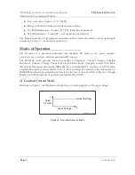
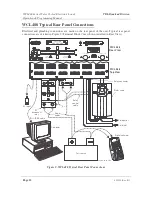
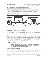
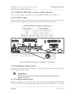
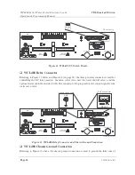
Each master load assembly or slave assembly has one inlet and one outlet water connection. They
are 1/2-inch NPT female thread. A multitude of adapters can be found at your local hardware
store if the connection size needs to be changed. Do not reduce the water lines below 3/8-inch
inner diameter, as improper water flow will result.
If you are using a “chiller” to regulate the water temperature, be sure to properly size the device
to match or exceed your cooling requirements. The specifications for the wattage capacity and
flow rates are provided from all chiller manufacturers. If your location can provide “processed
water” be sure the maximum pressure does not exceed 120 PSI.
Though the temperature graphs indicate that the load will operate to full power with only three
gallons per minute flow using 20ºC (68ºF) water, we recommend that the heat sink temperature
not exceed 60ºC (140ºF). This will provide a substantial margin for safety by lowering the stress
level on the power tray and extend the life of the product.
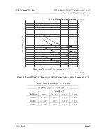
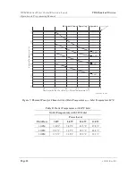
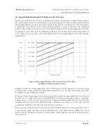
Thermal Transfer Characteristics
Figure 6 and Table C relate to operation at various flow rates with an inlet temperature of 10ºC,
based on power dissipation levels of 5, 8, 10, and 12 kilowatts. For the same type of operation
information with an inlet temperature of 20ºC, refer to Figure 7 and Table D.